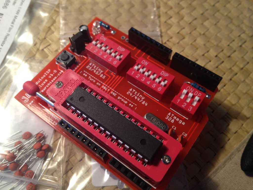
Tired of using a breadboard and setting it up with a crystal and caps every time I wanted to program a barebones ATmega328P or an ATtiny, I decided to make this shield.
Note: The ArduinoISP Deluxe Shield has a new name: TinyLoadr Shield! Read more about it here.
Update: The ArduinoISP Deluxe Shield has been updated with new features and an improved design! Check out the new blog post here.
The Problem
I like using a barebones microcontrollers in my projects as opposed to a whole Arduino. For one, it can cost a lot less, but it also allows you to make your projects smaller and more durable. The biggest problem I’ve found, however, is programming the microcontrollers.
When you get a new blank microcontroller, you need to do a couple things before it will start running your sketches. You need to set the fuses on it, and possibly upload the Arduino bootloader to it, and you need to be able to actually upload the sketches to the chip. Fortunately, the Arduino folks have a great tutorial on how to use your existing Arduino to burn the bootloader onto a new chip and upload sketches to it. Unfortunately, this method isn’t really that permanent. I mean yes, you can keep a breadboard set up like that and just plug it in when you need it, but to me it seems messy. I wanted to make the process easier.
The Inspiration
My inspiration for this project was when I’d ordered 10 new ATmega328P chips. I needed to burn the bootloader onto them before I could use them. The whole task just seemed tedious. I looked around and other people had already made shields that could program an ATmega328P. I also use ATtiny85 chips on occasion, and those are also annoying to program. I thought to myself, what if I could have one shield that could easily program my two most commonly used chips? I couldn’t find anyone who had done that before so I started designing.
The Project
At some point in the design process I decided to add support for a third form factor, the ATtiny 24/44/84 chips because, well, why not? (Update: ATtiny2313/4313 support added as well in v2.0 and v2.5) I also wanted to make sure that there was only one socket on the whole board. I wanted a ZIF socket because they’re super easy to insert/remove chips to/from, and there was no way I was getting 3 ZIF sockets on one board. I didn’t want to use smaller, normal sockets because they’re a pain in the ass to get chips out of the majority of the time.
The biggest problem I had when designing the board was how the end user would switch between programming the 3 different kinds of chips. In the beginning I wanted to have one jumper or switch that the user would toggle between. This proved pretty difficult to do given that building circuits is a fairly new hobby of mine and the 3 different form factors had very different pin configurations (eg, one had pin1 as GND while another had pin1 as VCC). In the end I decided to use simple banks of switches – when you want to program a certain chip, you turn on all of the switches in its bank and turn off the other banks.
How It Works
The shield’s circuitry is actually fairly simple. When you turn on a bank of switches, you’re basically just connecting the MISO/MOSI/SCK/SS/GND/VCC/RESET connections on the Arduino to the relevant pins on the ZIF socket. It’s as simple as that. The shield also automatically prevents the Arduino it’s attached to from resetting (using a small capacitor), which allows you to use the ArduinoISP sketch (included with the Arduino IDE) to program chips using the shield. There’s also a small LED on the shield that allows you to test out your microcontrollers using the “Blink” example sketch (also included with the Arduino IDE).

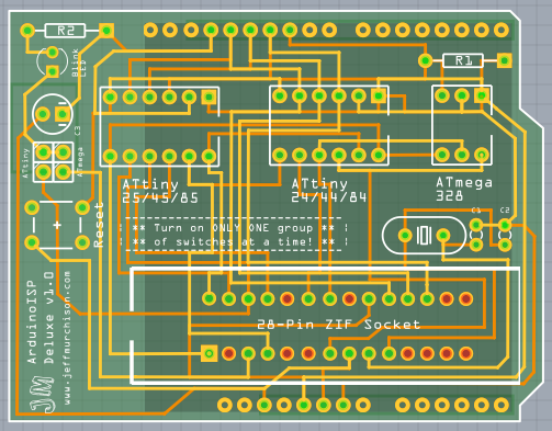
The final PCB layout for version 1.0 of the shield. Traces have since been moved and smoothed out (no right angles). PCB colour is also now black (more aesthetically pleasing).
The Finished Product
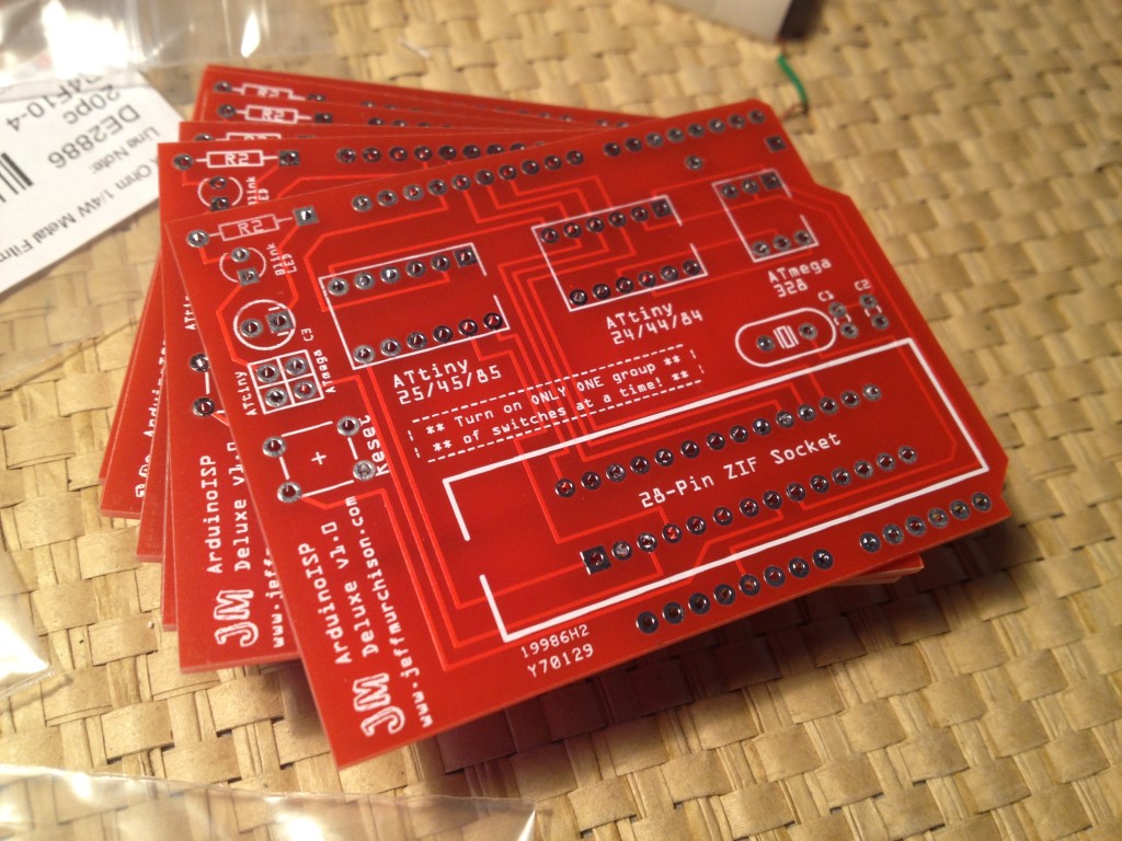
I wanted to have this as an actual Arduino shield, so I designed the whole thing using Fritzing. For those of you who are unaware, Fritzing is a very easy to use piece of software that allows you to make simple project diagrams, circuit diagrams, and even PCB layouts. I custom-made the part for the 28-pin ZIF socket and spent about a week arranging everything on the PCB before sending it off to iTeadStudio for printing. They have very reasonable prices for their PCB printing service, and as it turns out, the quality is pretty fantastic. Within 6 days my boards were already printed and in the mail. About two weeks later, I finally had them in my hands.
The boards have worked great so far, and they’ve already come in handy for reprogramming some of my projects that are still living on the breadboard. I learned a valuable lesson about the Arduino UNO and shields; if you want your shield to fit properly, get the *extra* long headers. With the “long, stackable” ones that I ordered, the bottom of my board was touching the metal of the USB connector.
Conclusion
In the end, it might seem like my solution to my fairly simplistic problem was a bit overkill. However, it was a good learning experience, and hey, it was another project for me to work on. And since I only needed one or two of the boards, I decided to sell the remaining ones as whole shields and hopefully recoup some of the money that I spent on getting the boards done.
If you’d like to buy one of the shields (complete with components), then head on over to my Tindie page!
———
Notes
In order to program ATtiny boards, you need to download some additional hardware libraries. A good place to get them for the ATtiny 44/45/84/85 and to learn how to install them is this page by the High-Low Tech Group from MIT’s Media Lab. You can also check out the Arduino Tiny Google Code page for even more hardware libraries.


I saw this on the exhibition section of the Arduino forum. I have to say it looks pretty slick, especially with the red components matching the solder mask. Nice one!
Thanks! When I found out that the ZIF socket and the DIP switches I wanted to use would be red, I decided to spend the extra $10 or so and get red-coloured PCBs. They came out better than I expected.
ArduinoISP Deluxe Shield Updated! | Arduino Projects
This thing is legit, I’m using it to program standalone AtMega 328s. Thanks Jeff!
Hi!
I am designing an Arduino shield for my “Arduino Coilgun” project (hey, stuff that shoots and/or gets explodey is FUN!), but I’m thinking I could make my circuit a lot smaller if I didn’t have to use the full Arduino but only used the actual processor…
How do you use the ATMega once you’ve programmed it? CAN you program it using the Arduino Java code and then just pop it into a circuit just like the ‘duino itself?
Sorry if these are noob questions, I’m a newbie!
–T
You’re absolutely right. You can shrink your circuit by using the microcontroller, some capacitors, resistors, and a crystal, instead of using a whole Arduino. You can also use a smaller microcontroller like an ATtiny to save even more space. Another big benefit is the cost – while it’d cost you $25-30 for an Arduino, you could build your own for less than $10.
As for programming it, you have two real options. You can program the microcontroller (using this shield, a programmer, or by hooking it up to your Arduino manually) and then put it into a socket on your circuit board, or you could add an ICSP header (like the one on the Arduino) to your circuit and program it that way.