Note: The ArduinoISP Deluxe Shield has a new name: TinyLoadr Shield! Read more about it here.
These are the build instructions for the ArduinoISP Deluxe TinyLoadr Shield kit. These instructions assume that the user has a basic knowledge of soldering. If you do not know how to solder, then check out this great guide by Sparkfun before continuing.
———
The following tools are used in this tutorial:
- Soldering iron (required)
- Solder (required)
- Wire cutters (required)
- Desktop vice (optional, but very, very useful).
———
First, ensure that you have all of the pieces of your kit. The kit includes:
- 1x
ArduinoISP DeluxeTinyLoadr Shield PCB - 1x 28-pin ZIF socket
- 1x 6-Pin female stackable header
- 2x 8-Pin female stackable header
- 1x 10-Pin female stackable header
- 3x 6-Position DIP switch
- 3x 10K ohm resistors
- 2x 680 ohm resistors
- 2x Bright blue LEDs
- 1x Bright red LED
- 1x Bright yellow LED
- 1x 16MHz crystal
- 2x 22pF ceramic disc capacitors
- 1x Pushbutton switch
- 1x 10uF electrolytic capacitor
- 4x 3-pin male headers
———
Click the photos for higher-resolution versions.
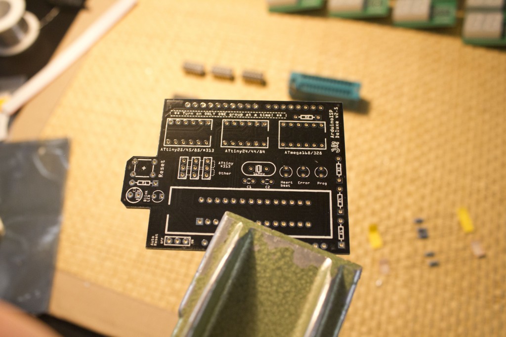
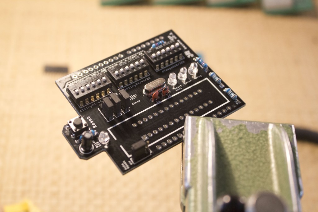
Start by placing your PCB into a desktop vice with the silkscreen side up.
When soldering to a PCB, it is a good idea to start with low-profile components, working your way up to the ‘taller’ components.
We are going to start by adding the 10K ohm resistors. They will fit into the R1, R2, and R3 spots. There should be two sets of resistors in your kit – a set of 3, which are your 10K ohm resistors, and a set of two, which are your 680 ohm resistors. The resistors can also be identified by the colour bands – brown, black, black, red, brown for the 10K ohm, and blue, grey, black, black, brown for the 680 ohm. Another way of identifying them is by using a multimeter to measure their resistance.
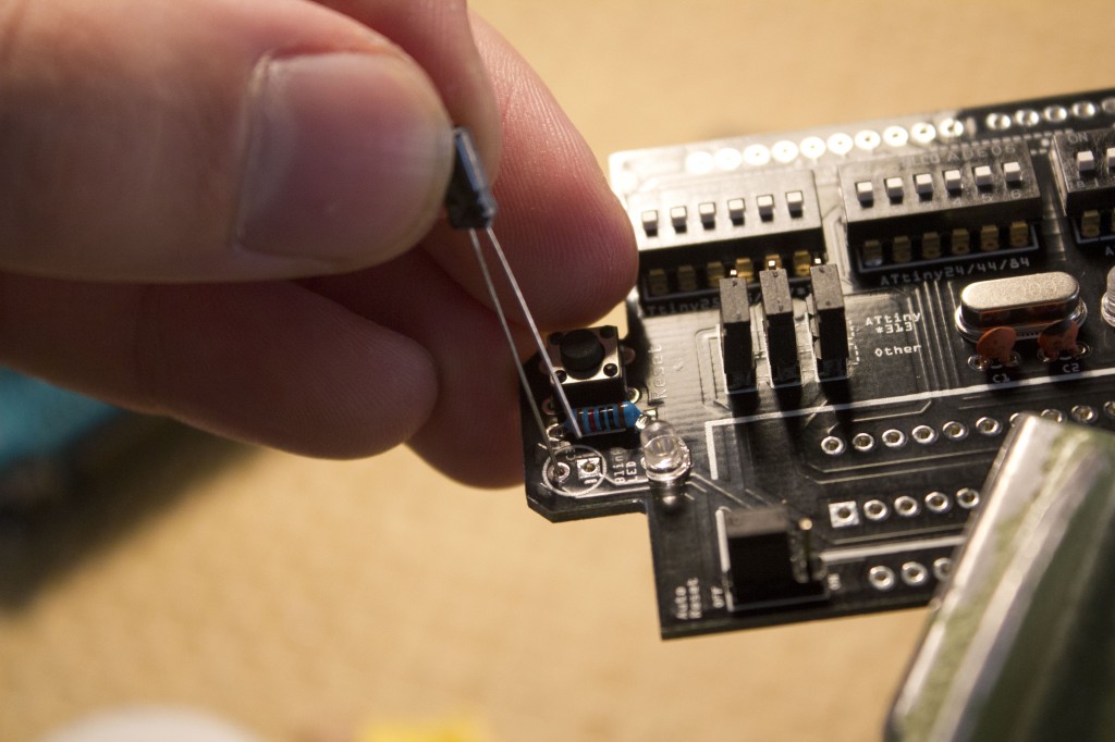
Start by bending the leads on your resistors at a 90 degree angle. Try and leave a bit of a wide bend like in the photo below. This will help the resistors stay in place a little better when the PCB is upside-down.
Insert the first resistor. Orientation is not important, as resistors do not have polarity, so don’t worry about inserting it “backwards.” If it is loose-fitting, then bend the leads on the other side so it can stay in place without falling out.
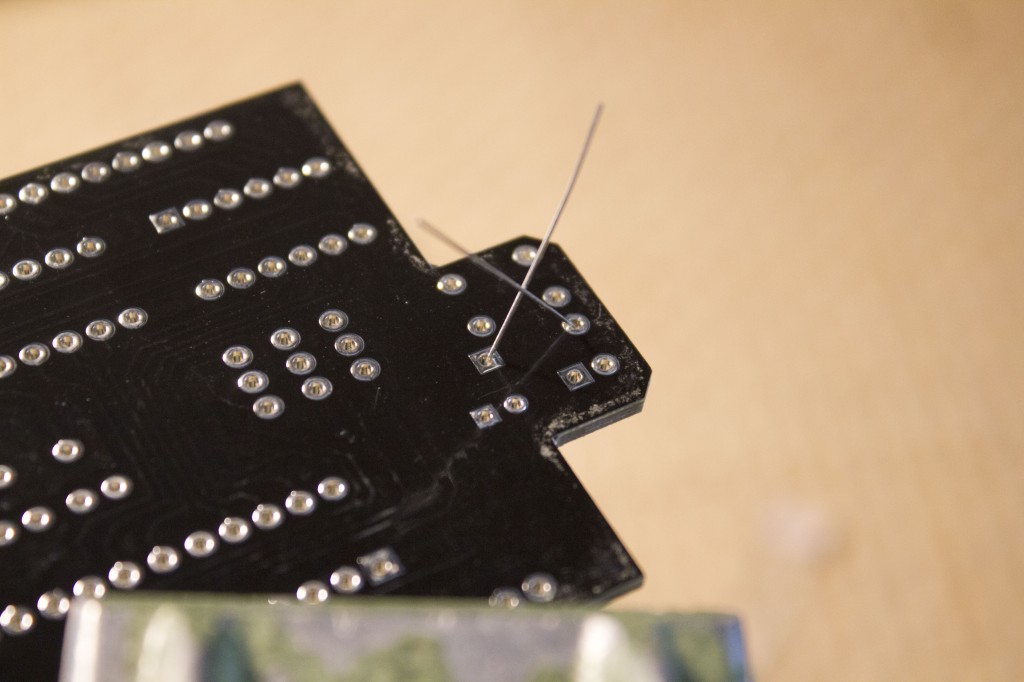
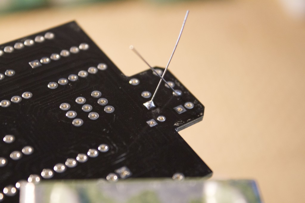
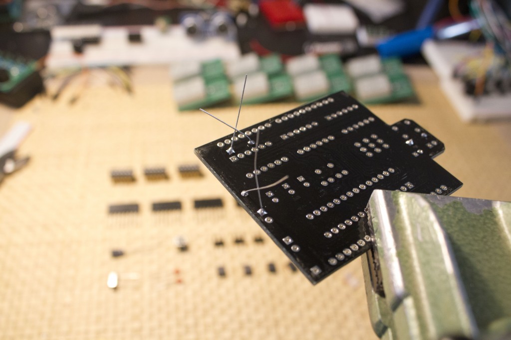
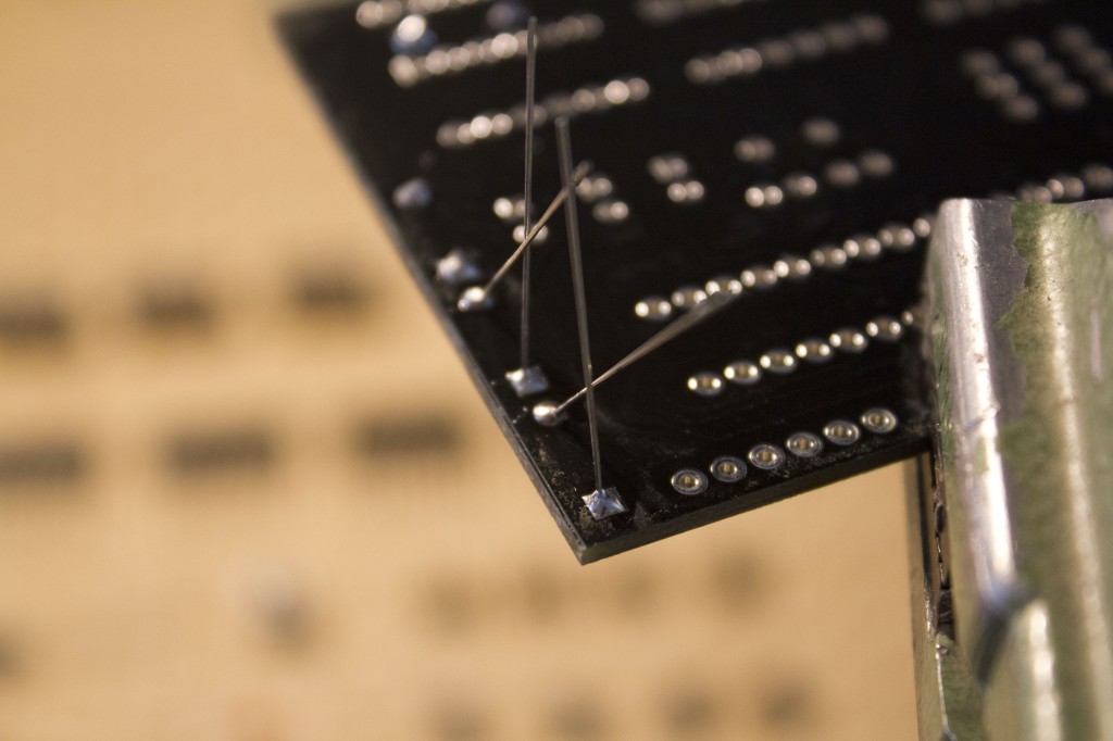
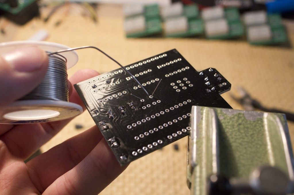
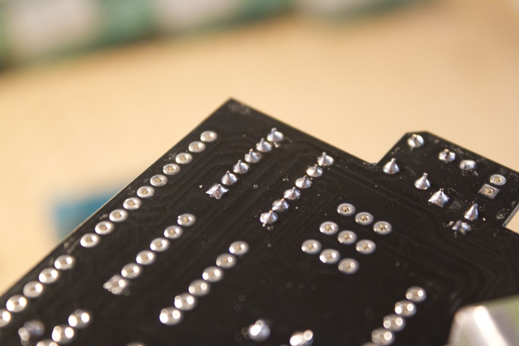
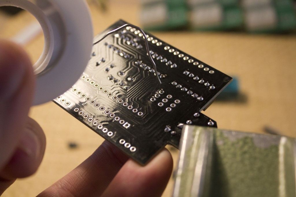
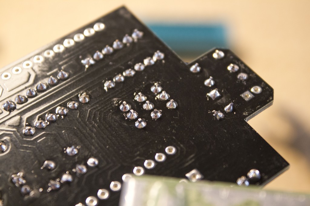
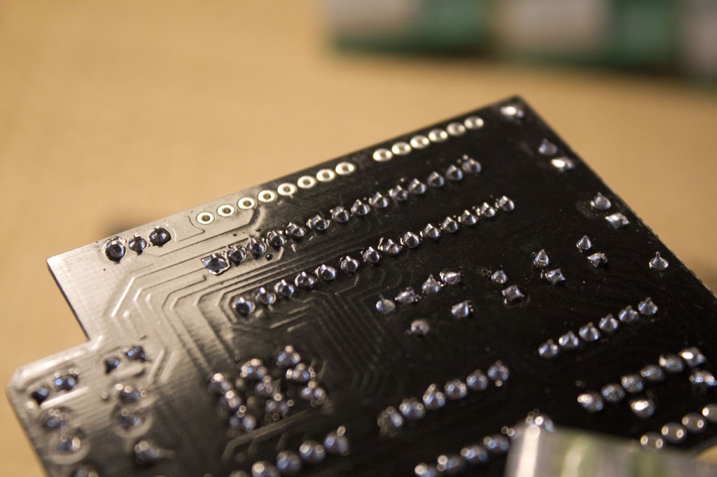
Remove the PCB from the vice and flip it over. If you can’t get your components to stay in place when upside down, try bending the leads. If that still doesn’t do the trick, then use a little bit of tape to hold them to the board. Solder the resistor to the board.
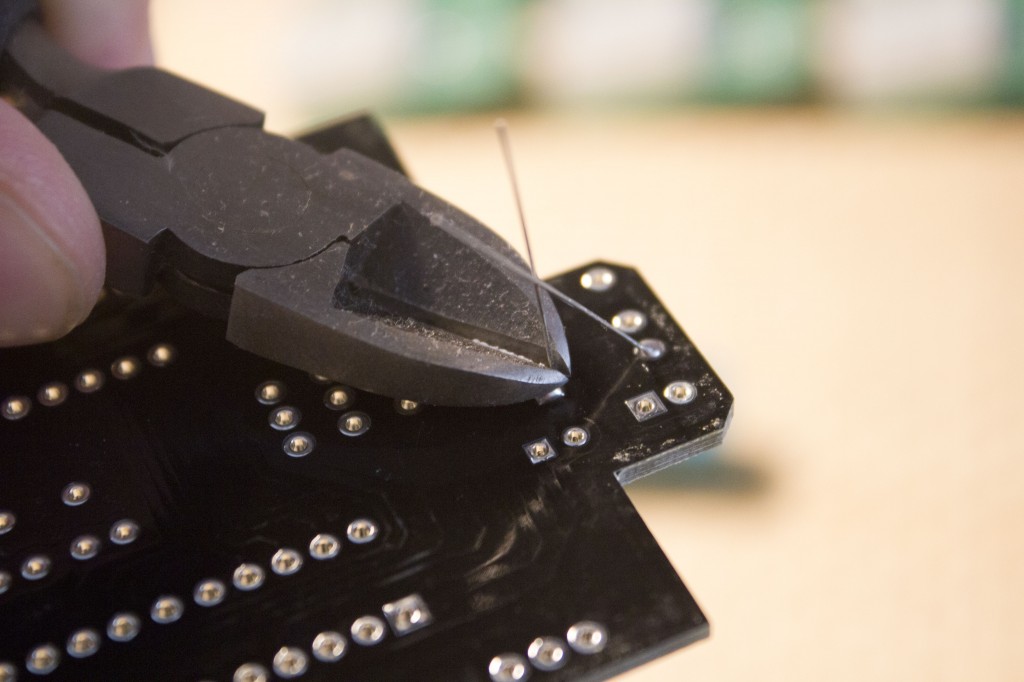
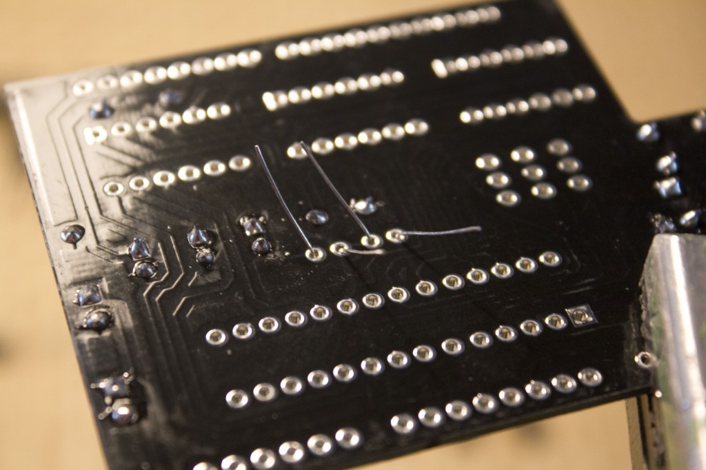
Now, we need to clip the excess leads. Using wire cutters, cut the excess wire off of the resistors as as close to the top of the solder joint as you can. Note that excess wire may go flying into your face when clipped, so either wear safety goggles, hold onto the excess wire while you snip it, or look away. Continue to cut the excess wire off of components as you solder more components on.
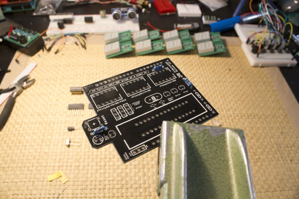
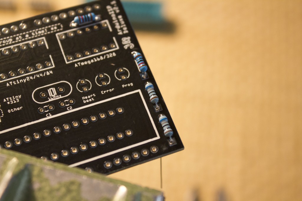
Repeat this process for the rest of the 10K ohm resistors in spots R2 and R3. When you are done, it should look like this.
We are now going to add the remaining 680 ohm resistors. They will fit into the R4 and R5 slots. Insert them and solder them in place.
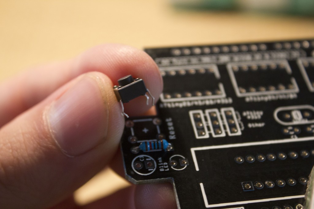
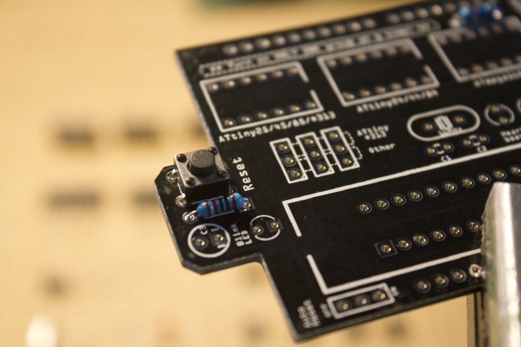
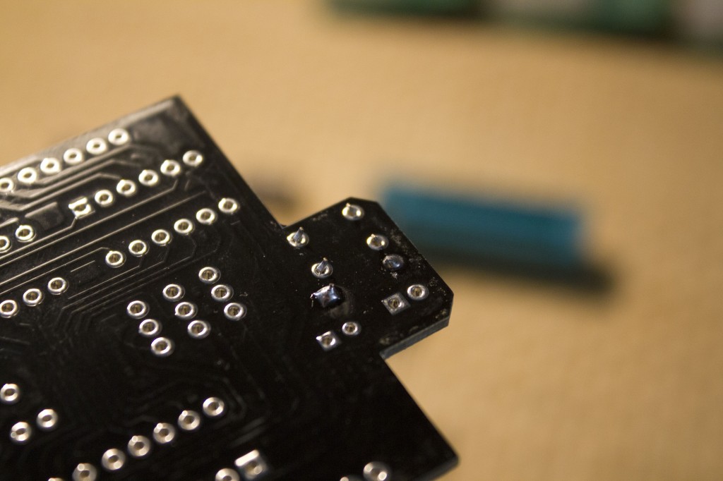
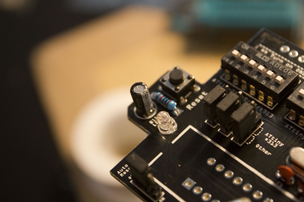
Up next is the pushbutton switch. It should snap into and stay in place very easily. Flip the PCB over, and solder it in place.
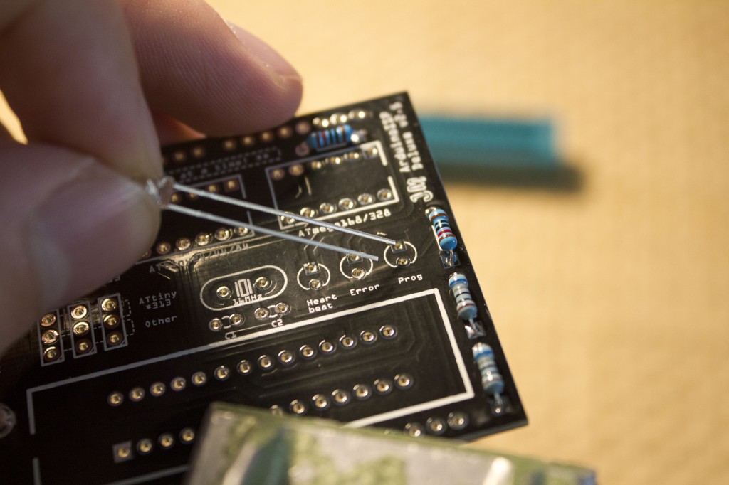
We are now going to add the LEDs. Each LED in your kit should be labeled with tape. Because the LEDs have a clear lens, it is recommended that you keep the labels on until you are ready to solder them in place.
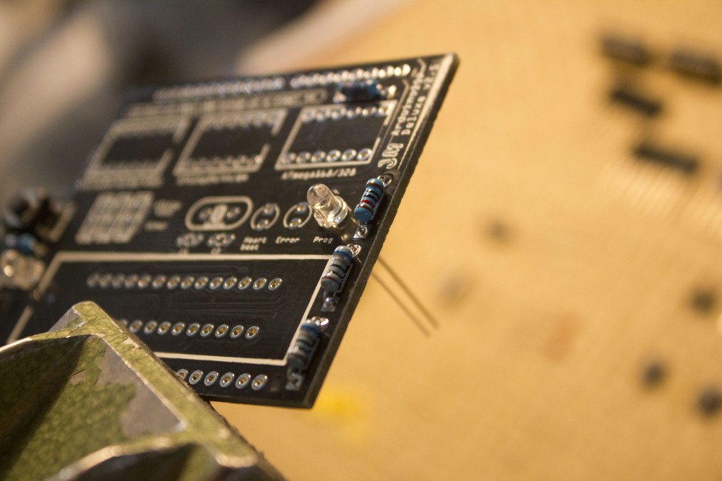
Start by taking one of the blue LEDs and inserting it into the “Blink LED” spot. Note that LEDs are polarized and must be inserted correctly in order to work properly. If you look at your LEDs, you will notice that one lead is shorter than the other. The longer lead will go into the square hole, and the shorter lead will go into the round hole. If you look even more closely at the LED itself, you should notice that the side with the short lead is slightly flat, and lines up with the white silkscreen on the PCB.
Bend the leads in order to help the LED stay in place while upside down.
If this doesn’t work, then you can use tape, or use your hand to carefully press it against the PCB while also holding solder in place like so (this is my preferred method):
Note that I’m using my pinky and ring fingers to hold the LED to the board.
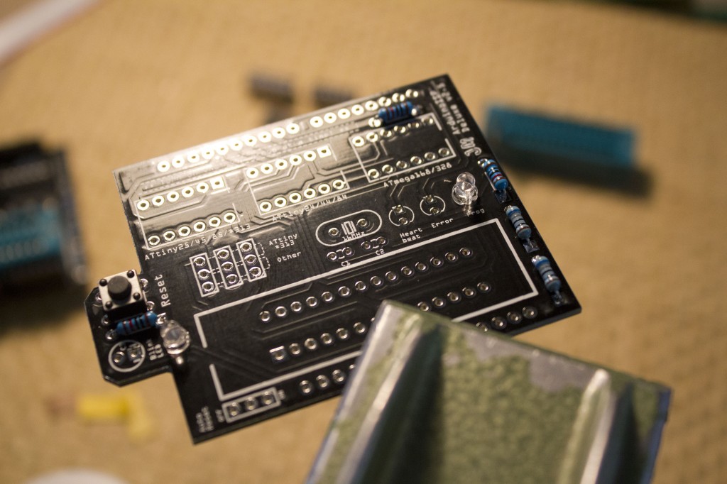
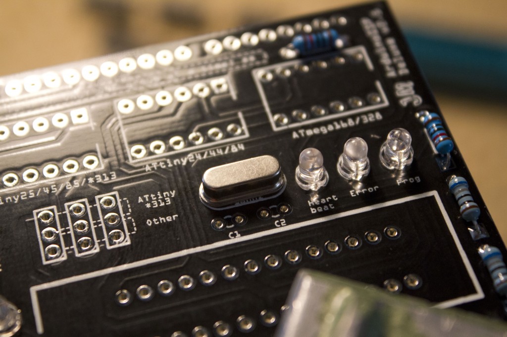
Take the other blue LED and insert it into the “Prog” spot and solder it into place.
Now, take the red LED and insert it into the “Error” spot and solder it into place.
Finally, take the yellow LED and insert it into the “Heartbeat” spot and solder it into place.
Now we are going to insert the 16MHz crystal. The crystal is not polarized so it can be inserted in any orientation. Bend the leads outward at first to help the crystal stay in place when the PCB is upside down.
Insert the crystal and then bend the leads out again. If the crystal still still doesn’t want to stay in place, you can use tape or hold it in place with your hand as demonstrated before. Solder the crystal in place. Tip: solder one lead, then flip the board over and make sure that the crystal is lined up with the silkscreen outline. Obviously this has no effect on performance, but it does help make your finished shield look nice!
After the crystal, insert the 22pF orange ceramic disc capacitors into slots C1 and C2. These capacitors are not polarized so they can be inserted in any orientation. Bend the leads or use tape to keep them in place while you solder them in place. Be careful when soldering these capacitors as they heat up very quickly.
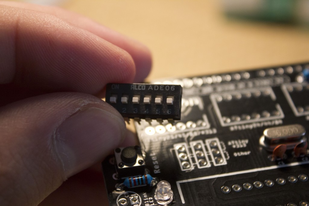
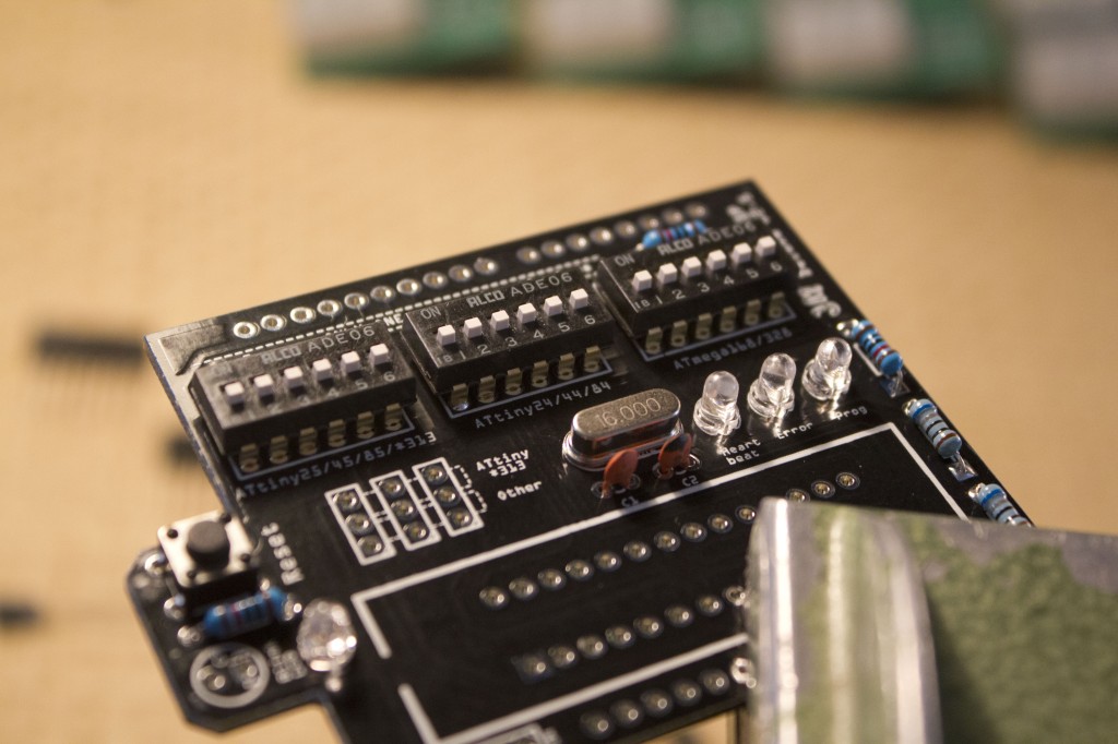
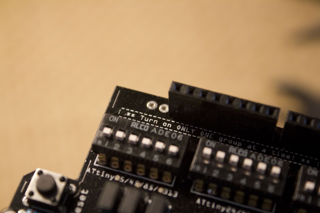
With the capacitors done, insert one of the 6-position DIP switches into its slot. Make sure that the switches are in the proper orientation. See the photos below for reference:
To get the switches to stay in place when flipped over, bend the pins on two opposing corners.
Then, solder another pair of opposing corners. Un-bend the pins and solder the rest.
Repeat this process for the other two DIP switches.
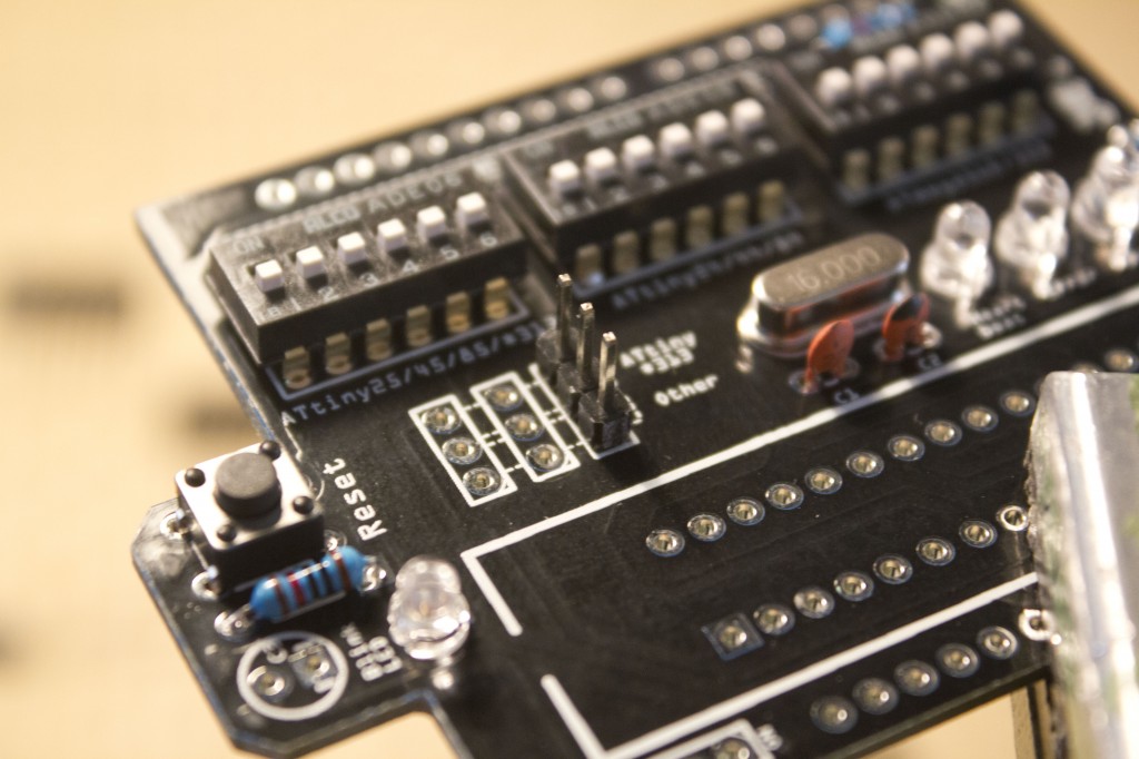
Insert one of the 3-pin male headers into one of the “Attiny2313 / Other” spots in the middle of the board.
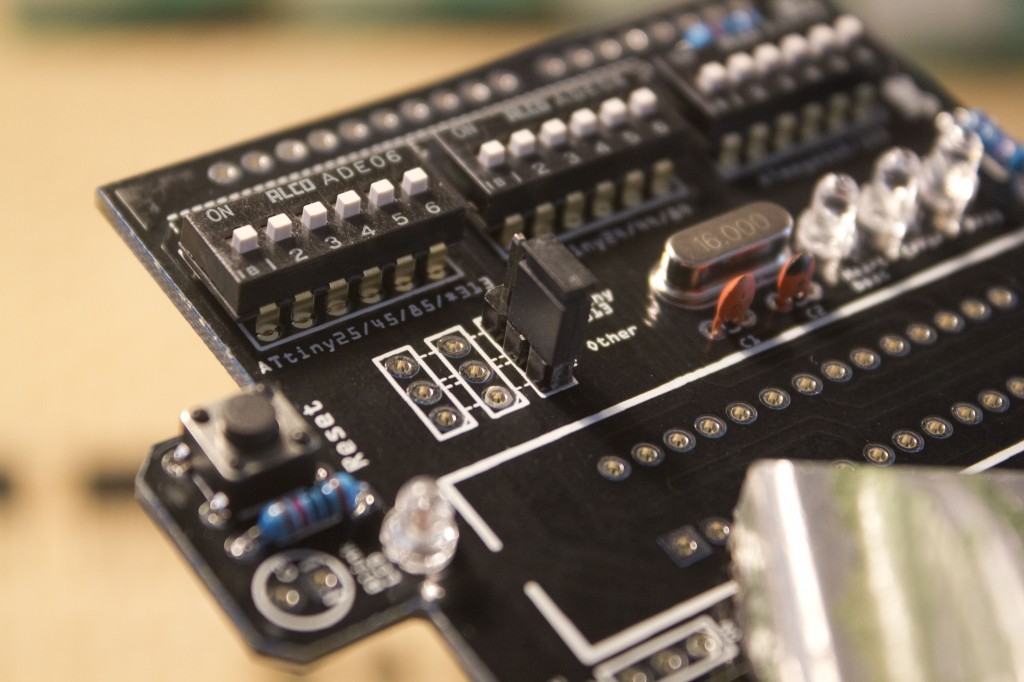
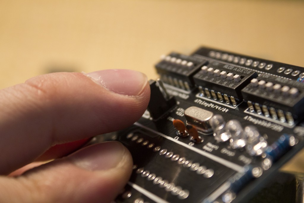
Place a jumper on two of the pins like so:
Now flip the PCB over and solder the header in place. To keep the header in place, you can either hold it in place with your finger while holding the solder:
or you can tape it in place:
Solder the rest of the pins, and then repeat this process for the rest of the headers, including the ones in the bottom-left corner of the PCB. NOTE: By default, you should set the bottom-left Auto Reset jumper to “OFF.” This enables capacitor between the ground and reset pins on your Arduino, allowing you to actually use the shield for programming purposes.
The next piece to solder is the 10uF electrolytic capacitor into the C3 slot. Note that electrolytic capacitors are polarized and will not work properly if inserted incorrectly. Insert the longer lead into the round hole and the shorter lead into the square hole. Bend the leads in order to keep it in place while soldering.
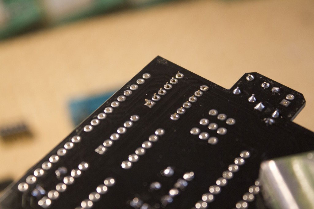
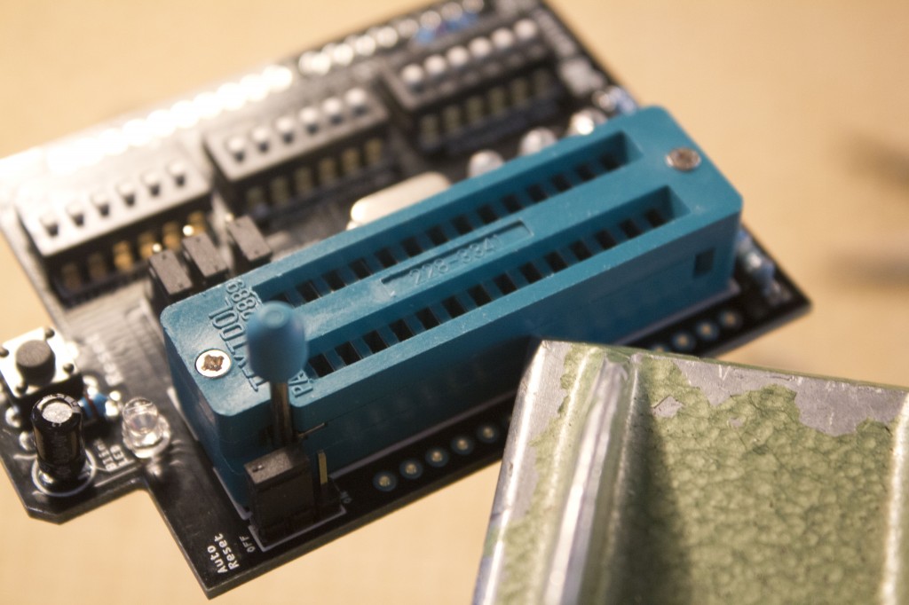
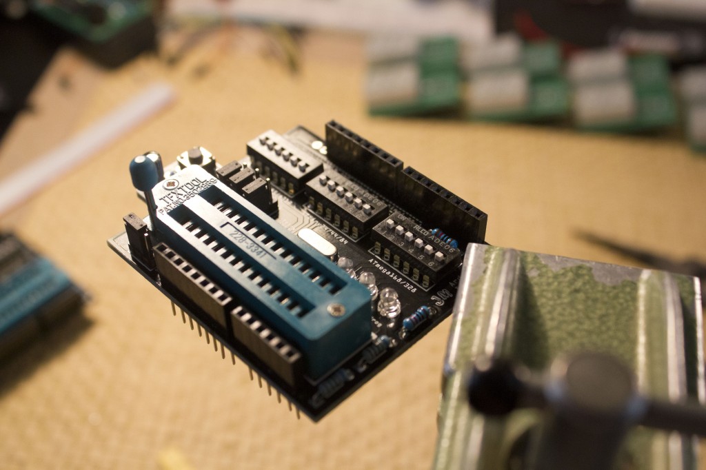
We’re almost done! Now insert the 28-pin ZIF socket into the PCB. Make sure that the locking handle is facing the left. Flip the PCB over and solder the pins. For the best results, keep the ZIF socket “open” (as in the picture below) while soldering.
The last things to solder are the female headers. At the “top” of the PCB, use the 10-pin header on the left and the 8-pin header on the right.
Note that the photo below is outdated and shows an 8-pin header where the 10-pin header should be. I’m working on getting a newer photo.
For the bottom left and bottom right headers, use the 8-pin and 6-pin headers respectively. If you have an earlier version of the UNO, you may have to clip the pins off of some of the headers as earlier versions had fewer pins.
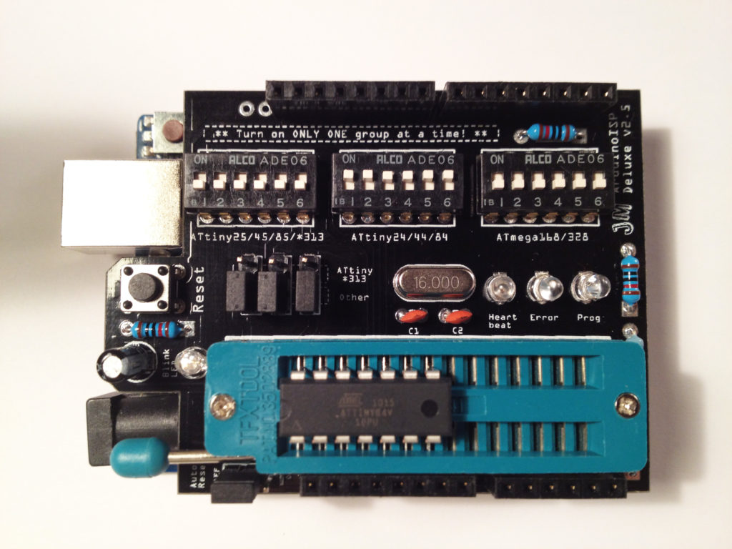
And with that, you’re done! Congratulations!
To start using your shield, you will need to take the ArduinoISP sketch (Open the Arduino IDE, File > Examples > ArduinoISP) and upload it to your Arduino. Then place the shield on the Arduino, set the appropriate jumpers and switches, and you’re good to go! Refer to the documentation that is included in your kit for more information. If you have lost your documentation or just want to have another copy of it, you can find it here.
If you have any questions, feel free to contact me.
















MAKE | The TinyLoadr Shield Programs AVRs From Your Arduino
The TinyLoadr Shield Programs AVRs From Your Arduino - IT Clips
Jeff,
I just got finished soldering the board using the instructions online and would like to note that your layout is perfect in placing the components from the closest ones to the board to the furthest. If you are now supplying the 10-Pin headers now I would remove the part about having to buy them separately. Probably a good idea too to add details on how you held the female headers in place for soldering. I had my wife actually feed the solder for me. Otherwise, so far this is an excellent piece of hardware.
Rgds,
Kevin
Also, you say to check the documentation that was supplied but I didn’t have any. I will just look online and print later if needed.
Thanks Kevin, I updated the bit about the 10-pin headers.
I’m not sure where I mentioned supplied documentation though, could you let me know where you saw that? I stopped including printed instructions quite a while ago.
Hi Jeff,
Just got a mail that my board is on it’s way. You say that you’re still need a new photo because yours is outdated. If you let me know what I need to put on the picture, I’ll might be able to send you the appropriate photo.
Cheers,
Michael