Note: The ArduinoISP Deluxe Shield has a new name: TinyLoadr Shield! Read more about it here.
Introduction
This tutorial will show you how to upload the Blink example sketch to an AVR microcontroller using the ArduinoISP Deluxe Shield TinyLoadr Shield.You can find instructions for all versions of the TinyLoadr Shield on this page. You can verify the version of your shield by checking the version number printed on the shield or by colour: v1.0 shields are on red PCBs, v2.0 shields are green PCBs, and v2.5 shields are black PCBs.
If you have not already installed additional hardware support files for ATtiny microcontrollers, you can get them from here. Installation instructions are included in the readme.txt file.
Click the relevant section below to expand.
[section=TinyLoadr v1.0 Instructions]
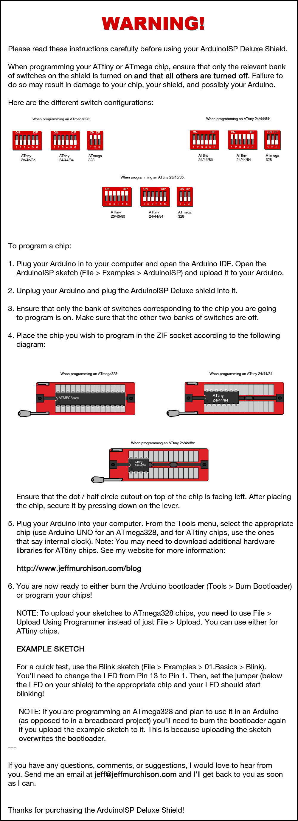
Click the image below to view the full-size version.
[endsection]
[section=TinyLoadr v2.0 Instructions]
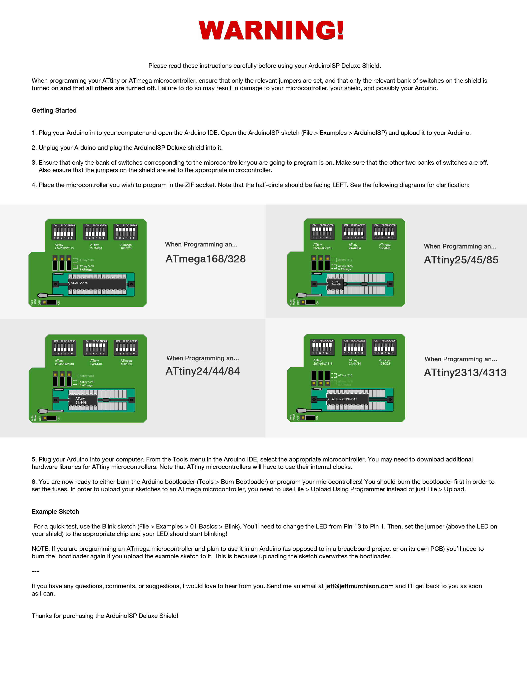
Click the image below to view the full-size version.
[endsection]
[section=TinyLoadr v2.5 Instructions]
Steps
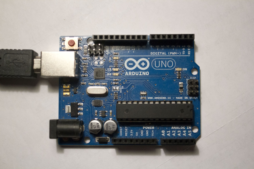
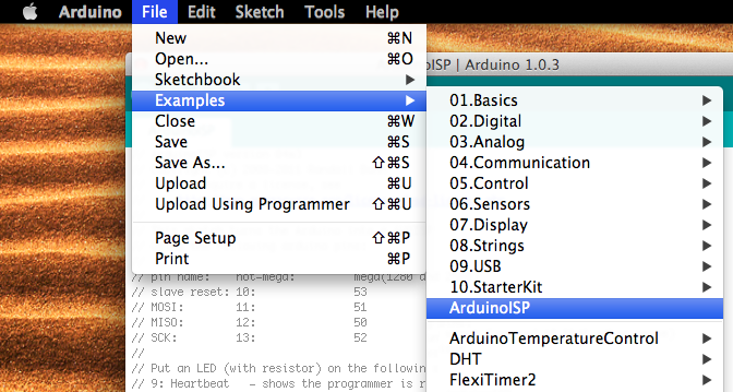
1. Plug your Arduino into your computer. Open up the Arduino IDE and then open ArduinoISP sketch from the File > Examples menu, and upload it to your Arduino.
2. When the ArduinoISP sketch is finished uploading, unplug your Arduino and plug the ArduinoISP Deluxe TinyLoadr Shield in.
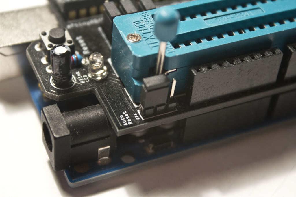
Note, you may upload the ArduinoISP sketch while the shield is attached to your Arduino, but you have to make sure that the Auto Reset jumper is set to ON or the upload may not work.
3. After the ArduinoISP sketch is uploaded to your Arduino, set the Auto Reset jumper to “OFF.” In the “OFF” position, sketches will be uploaded to the microcontroller in the ZIF socket instead of the ATmega328 on the Arduino.
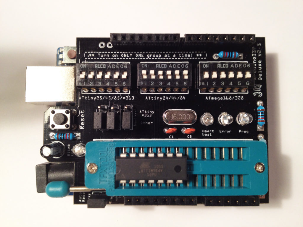
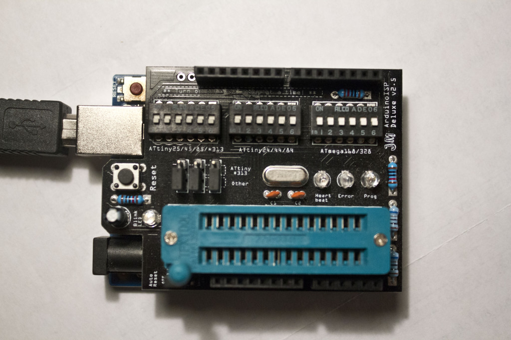
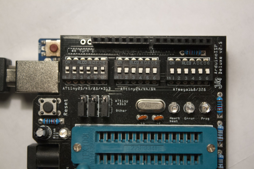
4. Set the switches and jumpers according to the microcontroller you wish to program. Ensure that only the relevant bank of switches is ON and all others are OFF. The image below shows the switch/jumper configuration for programming an ATtiny 24/45/85.
Warning: be sure the jumpers and switches are set properly before inserting your microcontroller. Failure to do so may result in damage to your Arduino, the shield, and the microcontroller.
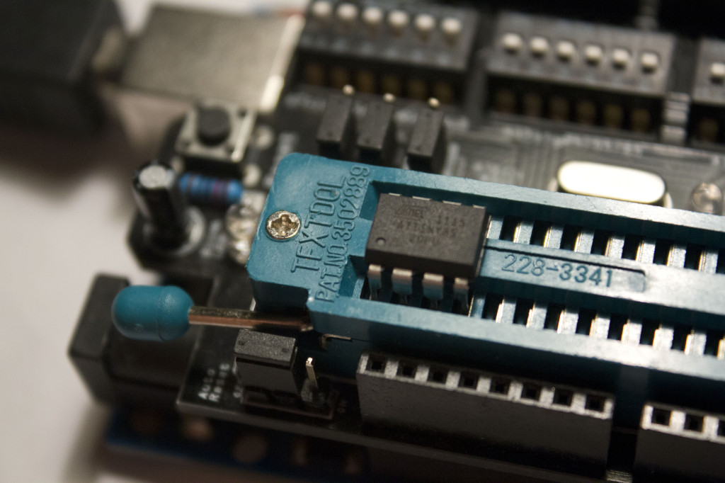
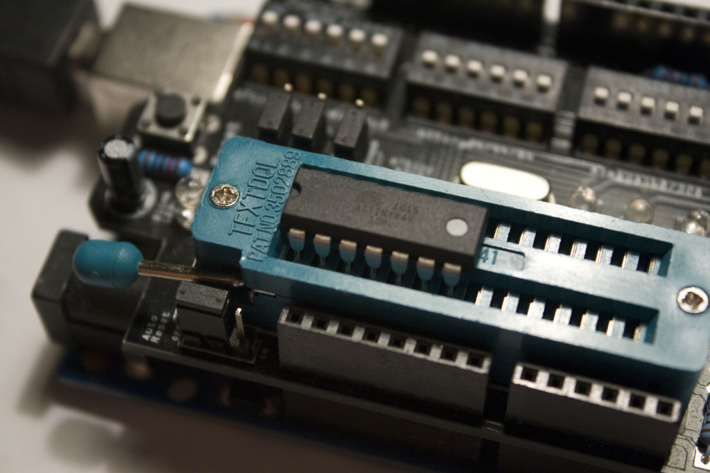
5. Insert your microcontroller into the ZIF socket, with pin 1 in the left-most contacts. Make sure that the dot or half-circle is facing the LEFT. See the photos below for clarification. Make sure that you insert your microcontroller properly, or you may damage the Arduino, the shield, and the microcontroller.
6. Plug the Arduino back into your computer.
7. Open up the Blink sketch from the File > Examples > 01.Basics menu.
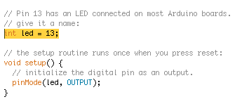
8. In the Blink sketch, change the led pin from pin 13 to either:
- Pin 1 for ATtiny24/44/84/2313/4313 or ATmega mircocontrollers
or
- Pin 4 for ATtiny13/25/45/85 microcontrollers.
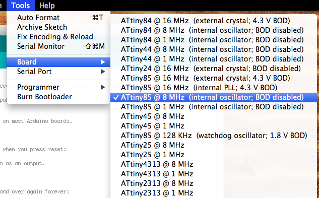
9. Change the board under the Tools > Board menu to the microcontroller that you will be using.
Note: for ATtiny microcontrollers, you will have to use the internal clock (either 1MHz or 8MHz) as there is no external clock source available on the shield. If you choose a different value then you may not be able to program the microcontroller with this shield again. ATmega microcontrollers can make use of the 16MHz crystal on the shield. If you are trying to program an ATmega328, you can select “Arduino Uno” as the board.
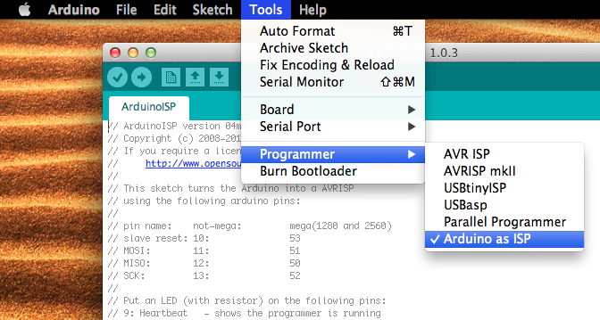
10. Under the Tools > Programmer menu, make sure you have “Arduino as ISP” selected.
11. If you are using a brand new microcontroller that has never been programmed before, then you will need to set the fuses on it and / or burn the Arduino bootloader to it. If you are not using a new microcontroller or have purchased one with a bootloader pre-loaded, then skip to step 12. If you are unsure, then just follow this step.
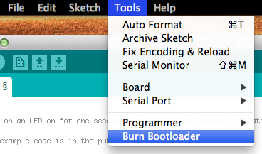
The fuses on a microcontroller are used to control things like clock speed, clock source, brown-out detection, etc. If you’d like a more technical explanation of AVR fuses, you can read a little more about them here, but in this tutorial we’ll just be using the default fuse settings. To set the fuses / upload the bootloader, you simply go to the Tools menu and select “Burn bootloader.” This process may take about 20 seconds.
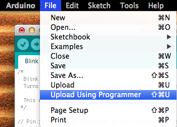
12. After setting the fuses, you can now upload the blink sketch. Go to File > Upload Using Programmer to upload the sketch.
Note: when programming an ATtiny microcontroller, you can simply use the regular “File > Upload” to upload your sketches. ATmega microcontrollers require you to use “Upload Using Programmer” or else it will try and upload your sketch to the Arduino your shield is plugged into.
And that’s it! You should now see the “Blink” LED flashing.
[endsection]
Programming Notes
- When your sketch is uploading to the microcontroller, the “Prog” LED on the shield will light up / flash. When it goes out, the upload is complete.
- The “Error” LED will blink if there is an error during the upload.
Note: You may encounter the following error when uploading a sketch, but feel free to ignore it:
avrdude: please define PAGEL and BS2 signals in the configuration file for part ATtiny85
If you encounter any other errors, double-check that you have all of the proper jumpers set. Also be sure that you have the microcontroller inserted properly into the ZIF socket, and that the shield is securely inserted into the Arduino.



I am trying to program an ATTiny2313 using the ArduinoISP Deluxe 2.5 and have been able to load the sketch to the arduino, then change the board to ATTiny2313 and LED PIN in the sketch, but when I upload the sketch, I get the following error. (I have the 2313 library.)
ERROR COMPILING.
In file included from Blink.ino:10:
/Applications/Arduino.app/Contents/Resources/Java/hardware/arduino/cores/arduino/Arduino.h:213:26: error: pins_arduino.h: No such file or directory
The heartbeat LED is throbbing, but no blinking LED.
Any insight is appreciated.
What cores are you using for the ATtiny2313?
Well, it seems I have the arduino core. Here is an image of my Arduino
http://i.imgur.com/EvlkI.png
and here’s my sketchfolder with the attiny cores. Are the cores meant to located in the correct place?
http://i.imgur.com/g9Z8k.png
TIA,
D
Hey David,
Sorry it took so long to reply, I’ve been insanely busy with work and your comment notification email got lost in my inbox.
I don’t think you have downloaded the correct cores. I recommend downloading the ones from the Arduino-Tiny project here:
http://code.google.com/p/arduino-tiny/downloads/detail?name=arduino-tiny-0100-0015.zip
Download those and install them in your Arduino/hardware/ folder and try the “Attiny2313 @ 8 MHz” option under Tools > Boards.
Arrived very promptly. Soldered on pins plugged in atmega328p set pins. Uploaded bootloader
and had heartbeat. This works great so far only have had one style mcu but will be trying 2313 real soon. I am thrilled about this because i have tried designing 3 different shields and none worked. After tones of frustration i purchased this hopeing it would work and was pleasantly surprised. By the way thanks for the fritz designs. I told guys at work i will replicate the design for them. Hope thats ok with you.
Glad to head that you like it! Obviously it’d be great if they bought ’em from me, but feel free to modify the shield’s design and make your own, so long as you don’t sell them. They’re licensed under the Creative Commons Attribution-NonCommercial-ShareAlike 3.0 Unported license.
Hi Jeff,
I got the board with the header for the crystal, thanks!
I have a couple questions.
1. The Blink LED on the board, how does that work?
2. Do I ever need to do anything with the auto Reset Jumper?
Thanks,
Tony
Hey Tony,
Glad to hear you got it!
1. The Blink LED can be used to test your microcontrollers. Just insert the microcontroller you want to program and then open the Blink example sketch that comes with the Arduino IDE. If you are using an ATtiny13/25/45/85, change the LED pin in the sketch to pin 4. For all other microcontrollers, change it to pin 1. Upload it to the microcontroller, and you should see the LED start to blink.
2. With the jumper in the “OFF” position, your sketches will be uploaded to the microcontroller in the ZIF socket. With the jumper in the “ON” position, your sketches will be uploaded to the ATmega328 on the Arduino itself.
Personally, I almost never switch it from the OFF position because if I need to reuse the Arduino I’ll remove the shield anyway.
Hi Jeff,
OK, thanks for the info I really like your shield.
You should have Sparkfun sell it.
But, make the crystal removable.
Tony
Got the kit, went together perfectly. Followed the instructions to load the sketch on the Arduino, ]programmed my VERY first of many ATTINYs. Thanks Jeff.
Jeff. Do any of the pins for the ZIF socket correspond to the breakout pins on
the opposite side above the DIP switches?
Yes, and they change when you flip the DIP switches. The SCK pin of the microcontroller selected goes to pin 13, MISO goes to 12, MOSI goes to 11, and RESET goes to 10. Here’s a helpful guide. Just note that on ATtiny*4’s, MOSI is pin 7. It’s missing that one for some reason.
Hey, the only functional LED on my shield is the blink LED. None of the others ever do anything during programming/standby.
Do I need a special ArduinoISP sketch?
Beautiful board, by the way. It’s otherwise fully functional and programming ATtiny/mega’s just fine. May I ask who does your PCBs?
Hey Connor,
I’ve sent you an email so we can troubleshoot the issue.
HI, I have the 2.5 version which works great under the Arduino IDE. Anyone know how/which to select it under ECLIPSE?
I was wondering if you have gotten anywhere with programming using Eclipse. I need to get that working as well. Thanks, Ira
Got the board and had it up and running in a couple of hours. I was a little surprised when I programmed a 328 that pin 13 didn’t blink the Blink LED, but the programmed device works fine when I pop it in circuit… and a 2313 blinks the LED when I switch pin 1.
A very nice kit!
Glad to hear you got it working! Pin 13 is used by the Arduino and microcontroller for programming (that’s the SCK pin) so when I designed the shield I didn’t want to introduce any issues by adding another LED on that pin.
You can get the Blink LED to blink with an ATmega328 by changing the pin to pin 1 instead of pin 13 (see step #8 above).
The TinyLoader Shield is the best. Makes programming a snap. Well worth the price.
Hi, I received your TinyLoadr Shield after 8 days to Switzerland in Europe. What a perfect service. It was also marked as a gift, which let it pass customs here without any additional fees (great). Thank you very much for this genius Shield. It worked from the beginning without any problems.
I love the Blink-Led which makes it easy to test the microcontrollers quickly.
Your shield replaces my “self-made” Attiny45/85 shield on a protoshield. With your shield I can program now all Attinys with one shield.
Thanks a lot.
Nelson
I was looking for 1 device to program the entire range of ATTiny chips when I came across the TinyLoadr and realized it was just shat I was looking for. I received the assembled version as a gift for Christmas (after a hint to my wife). I just programmed my first ATTiny and it worked perfectly first time. What an excellent programmer, I would recommend this to anyone who doesn’t want to wire up a breadboard to program the chip. Thanks Jeff for making this available.
Hi jeff
Very nice kit works fine but how can I erase the div chips completely?
kind regards willem
Jeff,
If you decide to do another revision of the TinyLoadr would you add a 220-ohm resistor to TX for all of the chips for your board? This will enable a serial connection to be used for debugging.
Rgds,
Kevin
I’m having problem writing to the 4313. Keep getting a lengthy message that basically says the board doesn’t exist even though its selected in the list?
I have no problem with the 2313. Any body else having this problem? I’m using the latest boards list from Google.
please advise.
I don’t have any 4313’s to play with but it looks like an outdated version of WinAVR is the issue. I’d post on either the Arduino.cc forums or on the issues section in the Google Code page.
I’m using the latest version from google 0100-0015.
Jeff I have been using the programmer successfully on atTiny 85 and 84 chips. Now I want to upload to a ATMEGA328P. For the life of me I can’t figure out what board selection I need to select after uploading Arduinoisp and putting the shield on a uno.
Hey Marty,
It depends on how you want to run your ATmega328. If you want to run it at 16MHz with an external resonator / crystal, then use “Arduino Uno.”
If you want to use it with the internal resonator (up to 8MHz) then you’ll have to download some new board definitions. You can find one here:
http://arduino.cc/en/Tutorial/ArduinoToBreadboard
I’d like to program an ATtiny13
In step 4, do I set the jumpers for an ATtiny*313 or an Other?
Been following this:
http://elabz.com/arduino-shrunk-how-to-use-attiny13-with-arduino-ide/
and used the “core13”