
This is part 1 of 2 in my post about my Arduino-Powered foosball scoreboard. Here’s a link to part 2.
At my office, we have a foosball table. There’s nothing really special about it. Rather there was nothing really special about it until last year. My boss and I play fairly often, and we had always joked that it would be cool to have the table keep track of the score for us, instead of us using the little abacus-style numbers on each end. I needed a new side project, so I challenged myself to build it.
Getting Started

Breadboard testing.
The first problem was a bit of a big one – I wasn’t an electronics person. Growing up, my dad always had LEDs, switches, and other components in his workshop, and I had learned the very basics about them, but that was over a decade ago. Plus this was going to be a lot more complicated than simply making some LEDs blink – there needed to be logic. I had kept hearing about the Arduino platform and decided that it would be a good starting point, and the scoreboard would make a great (if ambitious) first project.
After getting a starter kit for Christmas, I started figuring out what I needed to know to make the scoreboard a reality. I wanted 7-segment displays, so I learned how to wire them up to an Arduino. Each one used almost all of my pins (I was using 2-digit models), so I learned how to use the common 74HC595 shift register to drive multiple displays while not using up all of my Arduino’s pins. I decided I wanted the scoreboard to hang over the table like the jumbotron at a hockey game. To do this elegantly, I decided that there would be two units – one hanging above the table, and one below the table. The Arduino under the table would be responsible for detecting goals. When a goal was detected it would communicate with the main Arduino in the scoreboard itself, which would be responsible for actually displaying the score on the displays. To make them communicate, I needed to go wireless. I grabbed a cheap RF transmitter / receiver off of Sparkfun and installed those. After a lot of testing, I had a set of 7-segment displays and some buttons that I could wirelessly control them with.
Scoring
By far the biggest challenge I had during this project was figuring out how to detect goals. Each player has their own net, and their own ball return slot, so that made my life a little easier. My first idea was to use a PIR motion sensor (like you’d find in a home alarm system), but that was a dud. I played around with a couple of other ideas including an IR break beam sensor and a mechanical switch that activated when the ball hit the bottom of the ball return cup.
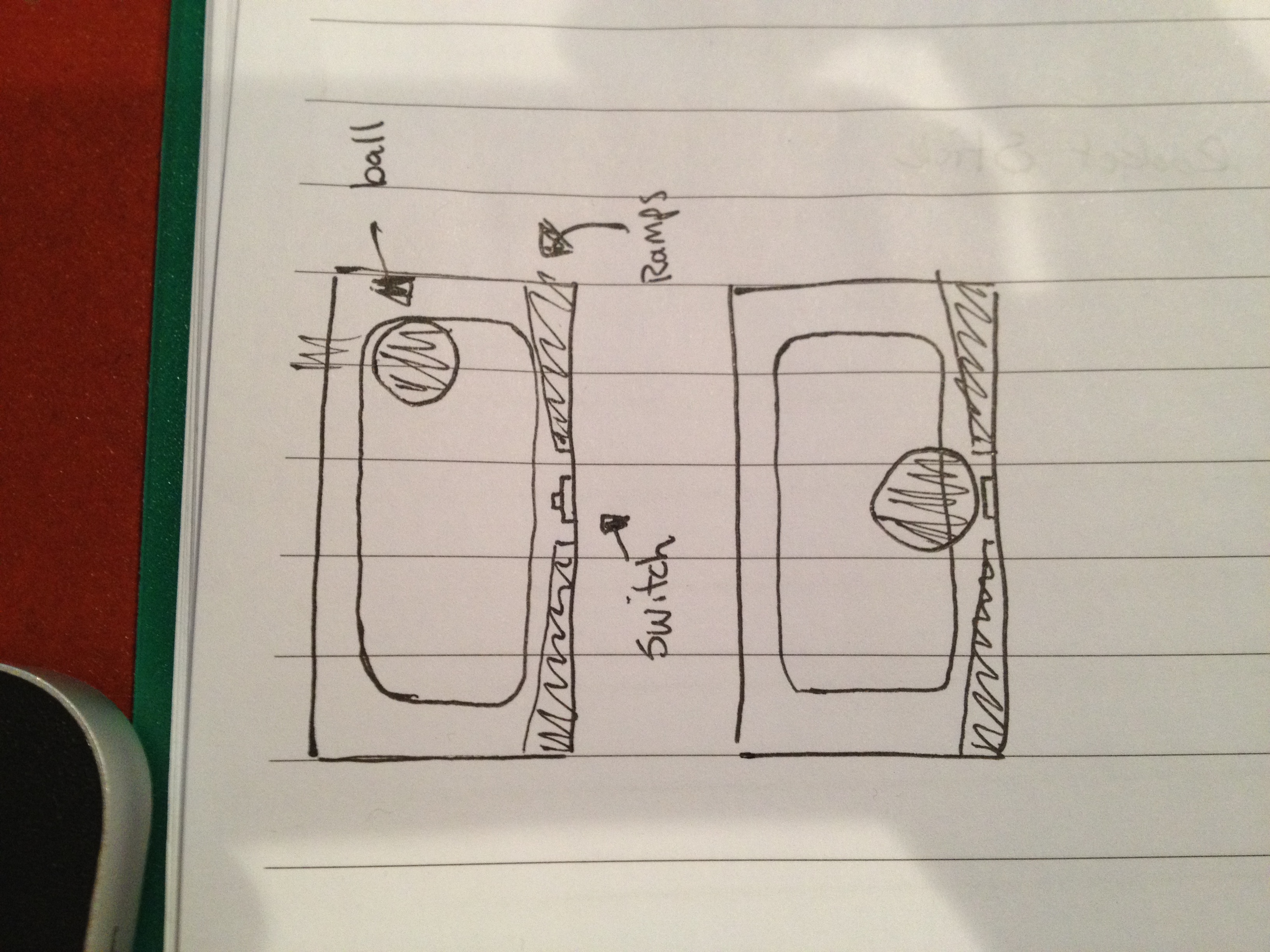
Goal-tracking idea, where the ball comes to rest on a switch.
In the end, I decided to go with a different kind of break beam sensor: a laser diode pointed at a photoresistor.

Closeup of the laser and photoresistor in a goal slot.
You might be familiar with a break beam sensor if you’ve watched movies like Mission Impossible, where a burglar has to sneak past an array of lasers without breaking any of the beams and setting off the alarm. The way it works is actually fairly simple. One lead from the photoresistor is connected to 5v, while the other is connected to GND via a resistor. The second lead is also connected to an analog input on our microcontroller. This creates a voltage divider, whose value can be read by the microcontroller. Here’s a schematic:
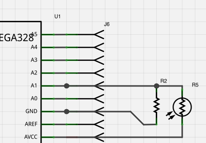
The voltage changes based on the amount of light hitting the photoresistor. When the laser diode is pointed at the photoresistor, it generates a fairly consistent reading. When an object breaks the beam and prevents the light from the laser from hitting the photoresistor, the reading drops until the laser’s beam can hit the photoresistor again. This drop means that something interrupted the beam (in all likely cases, the ball) and the scoreboard registers a goal. The inside of each goal post was outfitted with a laser diode and photoresistor. The depth of the ball return slot is less than twice the diameter of the ball, which means that if the beam from the laser went exactly across the middle, the ball would always pass through it when a goal is scored. As a bit of a safety I put the laser and photoresistor an inch or so down the slot to prevent any false readings when a ball gets very close to the edge of the goal post, but doesn’t go in.
Here is a video that I made which demonstrates how it works:
Here i
Making It Work
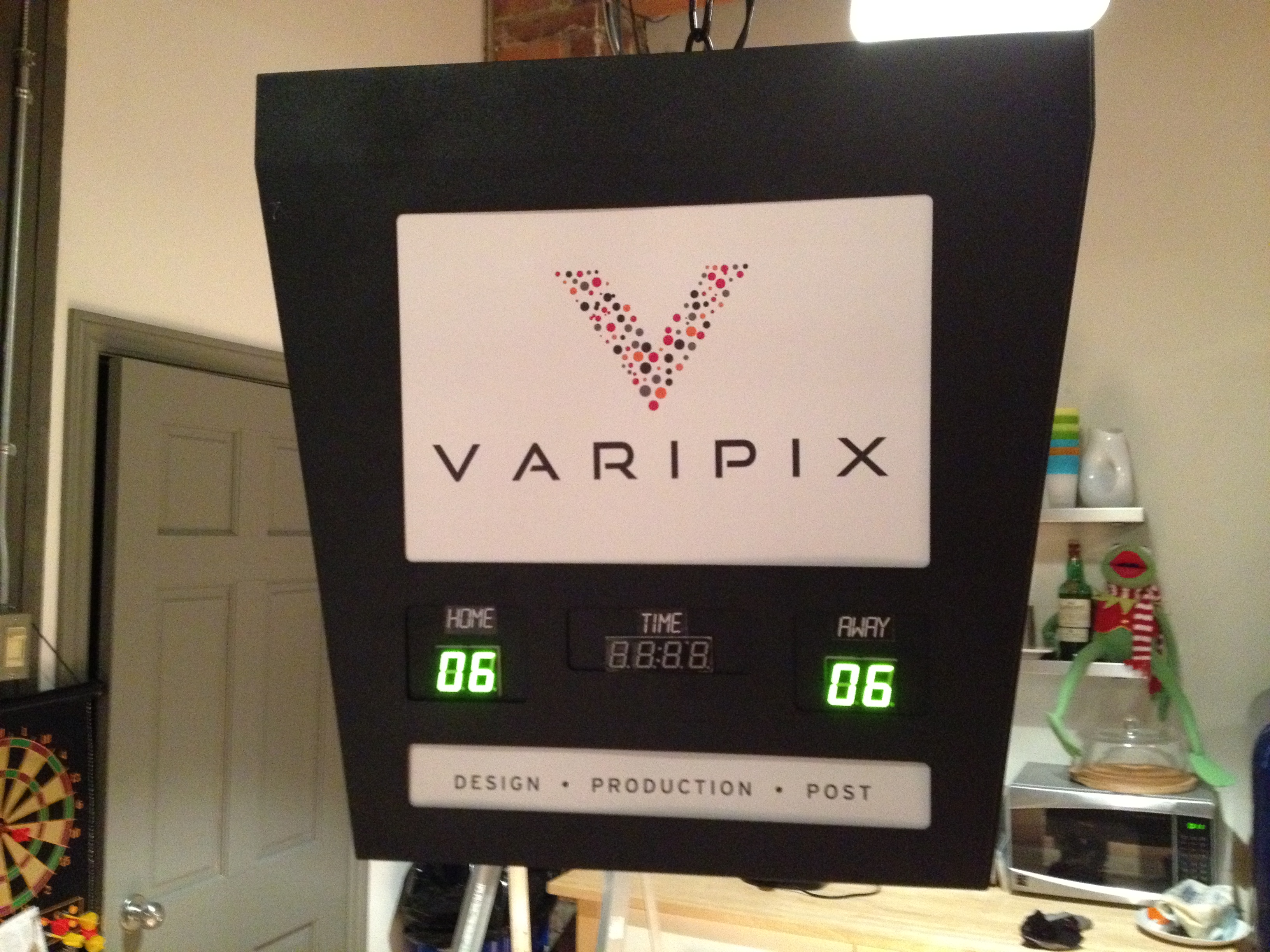
For the scoreboard itself, I instantly knew the perfect enclosure – an old NHL scoreboard lamp. For those of you who didn’t grow up here in the Great White North, these were simply metal hanging lamps that had the logo of several different NHL hockey teams on them. The lamps themselves were shaped like a generic jumbotron, showing the score of the home and away team on all four sides.

Example of one with the Vancouver Canucks logo on it.
I found one of those lamps on Kijiji and modified it to fit my electronics. This basically involved removing the old plastic and finding a way to mount the 7-segment displays. I got my dad to cut some display holders for me on his scroll saw. After making sure they fit, I painted them black to match the scoreboard frame. After adding some HOME and AWAY labels, it was ready to assemble. The assembly process basically involved a lot of glue, patience, and wiring. It took about an hour or so to get everything inside the enclosure and hooked up properly. But in the end, it looked awesome. Well, the outside looked awesome. The inside was a rat’s nest of wires that I’m almost too embarrassed to show (keyword: almost).
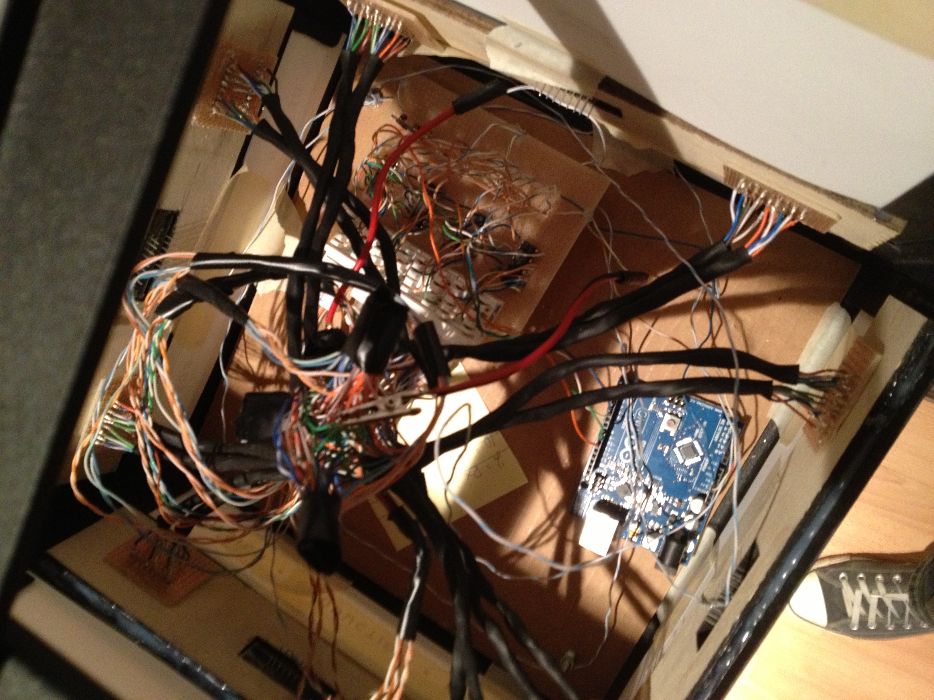
The horrible ratsnest of wires that was the first version of the scoreboard. Note the exposed alligator clips and bare wires running into an Arduino board.
Testing
The Arduino under the table was running the laser diodes and checking the readings of the photoresistors. I spent many afternoons firing ball after ball at the goal post, tweaking my code for the best results, and making sure that it wasn’t too sensitive to interference (shadows, light changes, or people bumping the table). Eventually, the table was running stable enough to show off to others. I also decided to add some manual control buttons, just in case there was an accidental goal, or if there was a problem with the lasers and the goals had to be entered manually.

Closeup of the buttons and an incomplete version of the bottom unit.
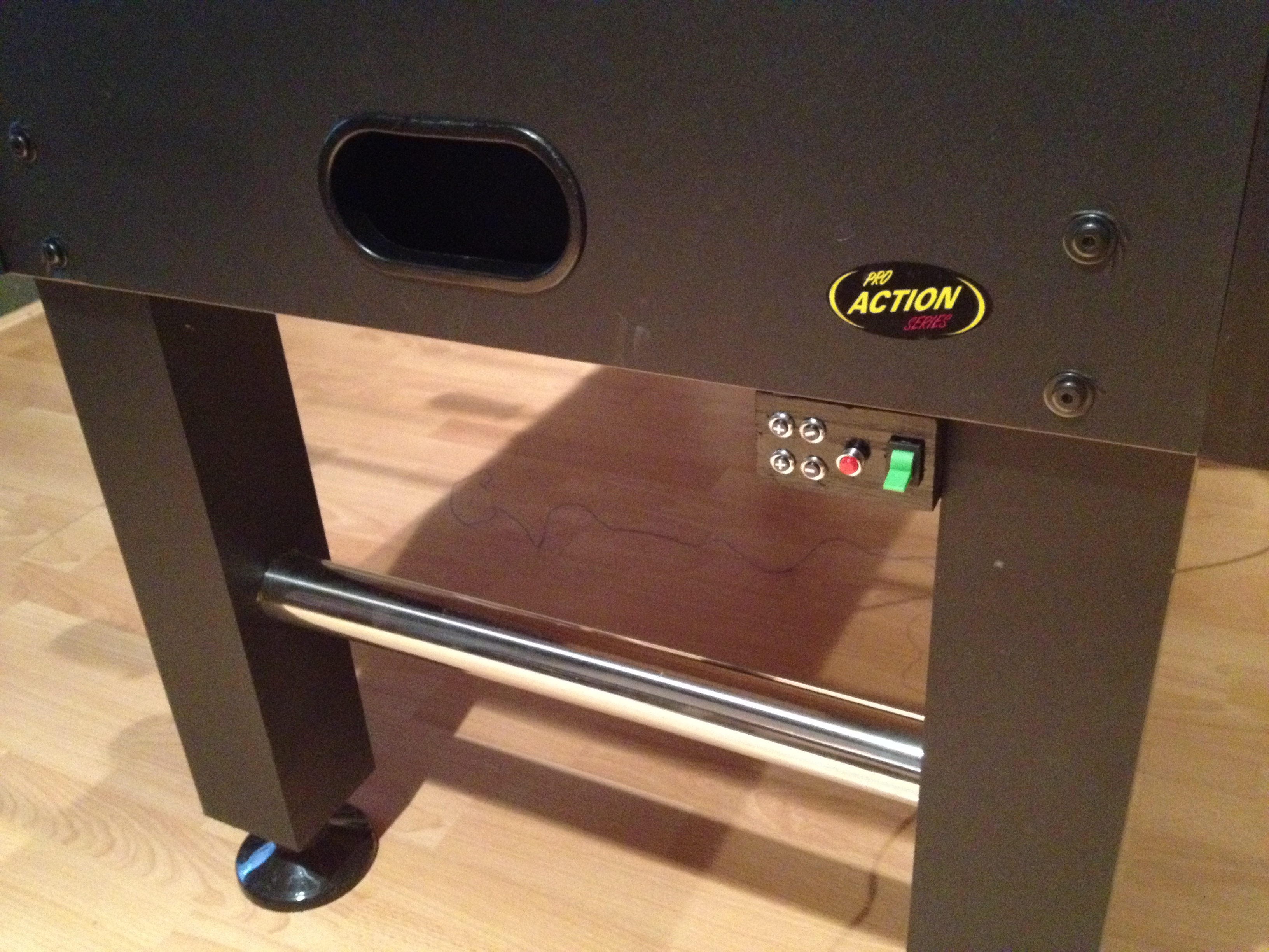
Button controls (+/- for each player, reset, and power switch for lower unit).
I got a great response from everyone I showed it to. People couldn’t believe that it was my first Arduino project, but it was. From planning to final working model, it took just under 3 months of non-continuous work (it was the busy season at work so I mostly spent my evenings and weekends working on it). I knew that the project wasn’t perfect, and that there were areas where it could be improved (the wiring, for example). I let it be for time being, because it looked cool, and functioned well, but I knew that it would eventually have a second version. (Part 2 of this blog post is now up!)
Here’s a video of me demonstrating the table and scoreboard:
And here’s a gallery of everything from the beginning prototyping to assembly. Hit the “info” button for photo descriptions:
[flagallery gid=3 w=518 h=550 skin=phantom]
I did some work with LDRs when I was at school and found that they suffered a lot from ambient light issues. However as long as it’s nice and dark in the bottom of the goals you should not have any issues.
Yeah, that’s an issue I struggled with when I brought the table to a couple of Maker Faires – there was much more ambient light than in my office.
Even now in my new office there’s more ambient light than before (it’s underneath 4 skylights now) so my plan is to recess the LDR into the wood a little more so that even when light goes into the goal posts, it won’t affect them.