

This is part 2 of 2 in my post about my Arduino-Powered foosball scoreboard. Here’s a link to part 1.
After building the first Arduino-powered foosball scoreboard, I was really excited. I showed it off to coworkers, friends, and family, and I also posted about it online. I got some great feedback, and started thinking about ideas for a possible revision in the future. Eventually though, I kind of forgot about it and moved on to other projects.
About 8 months after finishing the scoreboard, I started revisiting the idea of a new version. When I looked at the ratsnest of wires, I was a embarrassed. Not only did the wiring look terrible, but the actual circuitry wasn’t well thought out. In fact knowing what I know now about electronics, I’m surprised the thing even worked as well as it did. After all, there wasn’t a single current-limiting resistor to be found in the whole project (seriously). It was going to need a major overhaul, but I was ready to make it happen.
Custom PCBs

So much cleaner.
TThe first thing I wanted was to design my own PCBs for the revised version. When I first posted the scoreboard online, one person commented that I shouldn’t use a whole Arduino in my final project. I understood where they were coming from. An Arduino is big, expensive, and overall, is just a prototyping platform.
A couple of months after finishing the scoreboard, I got rid of the Arduino in favour of a bare ATmega328 on some perfboard. As it turns out, it is pretty easy to move from an Arduino to the bare ATmega microcontroller (I even went so far as to make an Arduino shield to help me program bare ATmega and ATtiny microcontrollers).

The revised under-table unit. ATmega328 running at 16MHz, with a 433MHz wireless transmitter, an LED and buzzer for goal indication, voltage regulator for power, and terminal blocks for connections to buttons and lasers / photoresistors.
But to me, that still wasn’t good enough. For a couple of smaller projects, I had learned to design my own PCBs in an application called Fritzing. Fritzing made it super easy for a beginner like myself to place the components, link them up, and generate gerber files that could be sent to a PCB fab. They even have their own PCB fab, but it was a bit too expensive so I found some alternatives in China where the cost was very reasonable (about $1 – $3 per board in quantities of 10).
Better Connections
No more messy wires everywhere, and much easier to add/remove.
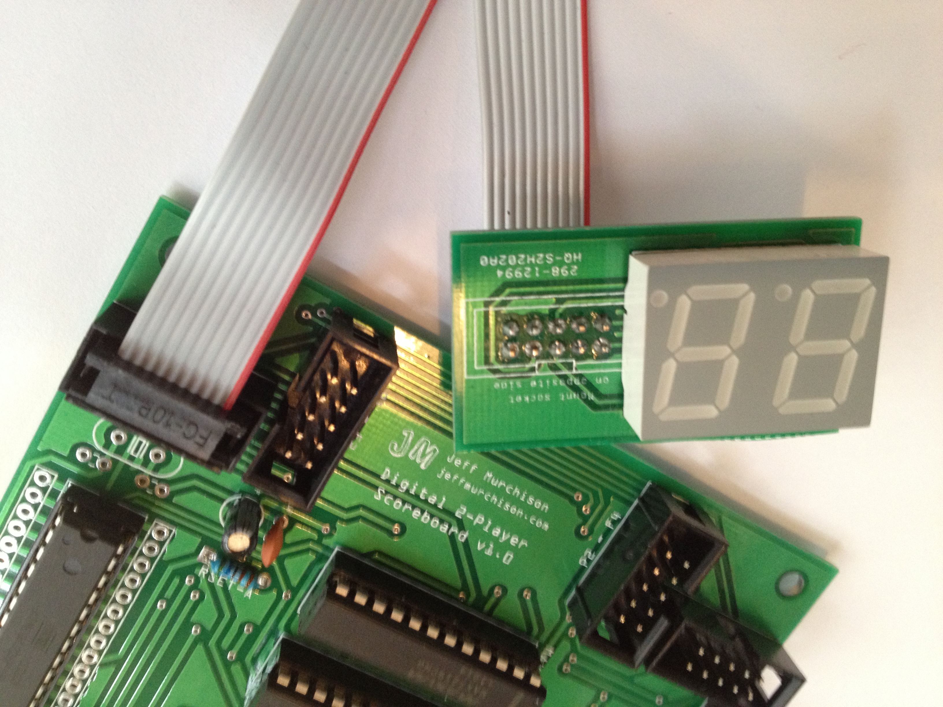
OneOne thing that caused the large ratsnest of wires in the receiving unit was the poor connections between all the displays. Not only were they unreliable, having to be resoldered every now and then, but they were a royal pain if a display needed to be removed or fixed or what not. Also, my choice of wire was not the greatest. I decided that the new displays would be very modular, using standard IDC connectors and ribbon cable.
Get rid of the shift registers

MAX7219/7221: More powerful than shift registers and even easier to use.
While shift registers are good tools to use, they aren’t always the best option for driving large amounts of LEDs. A better option is an LED driver. An LED driver is basically a shift register that is specifically for driving LEDs.
The LED driver that I decided to use in the new version of the scoreboard is Maxim’s MAX7219. This LED driver is capable of driving up to 64 LEDs, or eight 7-segment display digits. The MAX7219 can be daisy-chained just like the 74HC595 shift register, and I took advantage of this because I needed to drive 16 7-segment display digits (2 digits per display, 2 displays per face, 4 faces).Whi A
Another nice feature of the MAX7219 is that it only requires one current-limiting resistor for all 64 LEDs. This is because the MAX7219 uses multiplexing so technically only one LED is on at a time. The LEDs switch on/off so quickly that it is impossible for our eyes to see.
%h
Better Wireless Connectivity

nRF24l01+: More cost-effective, smaller footprint, and easier to use.
While the wireless RF units worked, they weren’t perfect. For one, they were simply a transmitter or a receiver. If I wanted bi-directional communication, I would have had to buy another transmitter/receiver pair. Another issue was that they were kind of expensive (around $10 a pair). After doing a bit of searching online, I found the perfect replacement wireless module: the nRF24l01+. Not only was it cheap (around $1 each in quantities of 10), but it was a transceiver, meaning it functioned as both a transmitter and receiver. To top it off, there were already some well-written Arduino libraries for it.
Better Overall Design
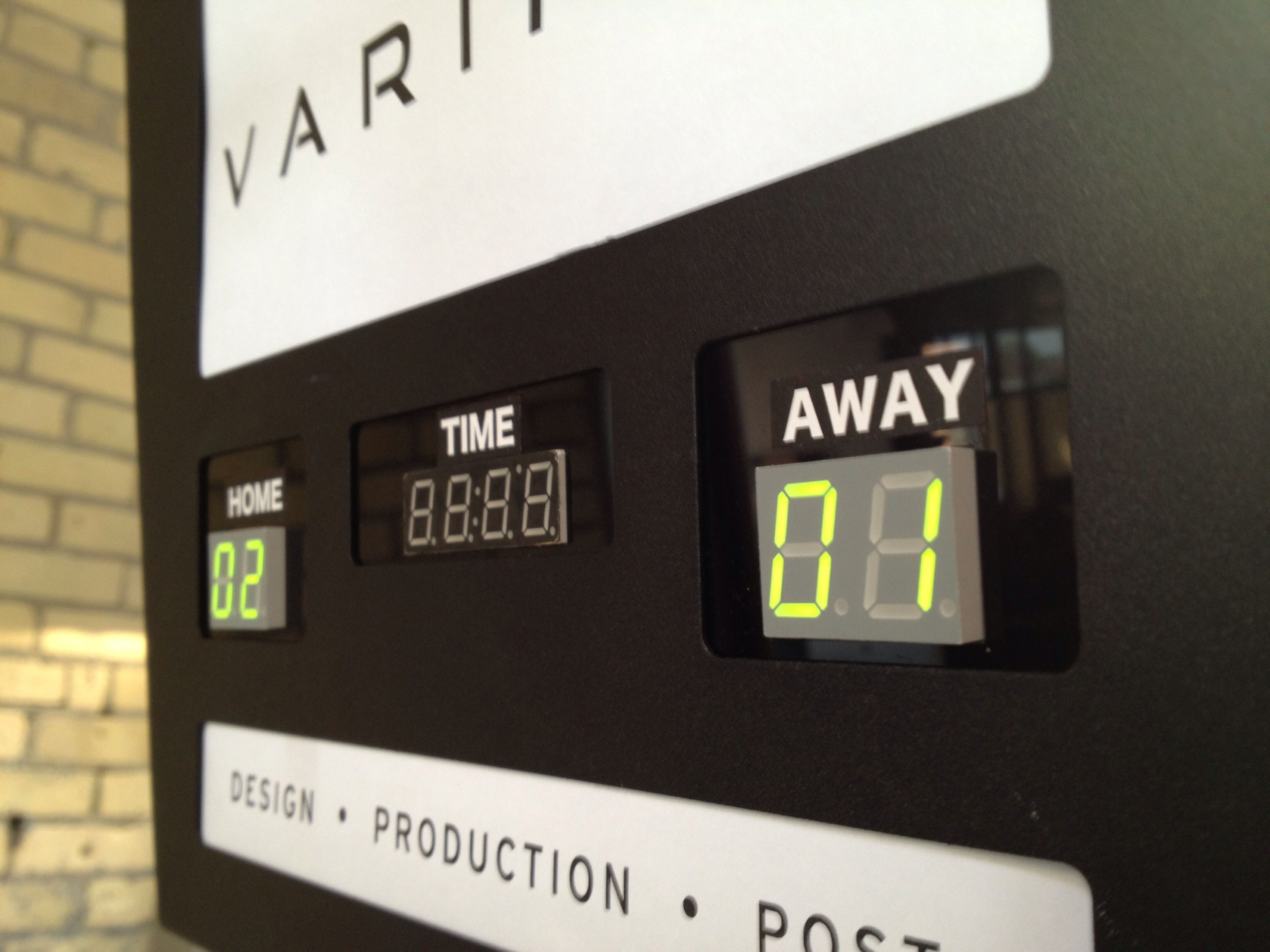
Sleek laser-cut acrylic faceplates from Toronto Laser Services.
There were plenty of small things that I wanted to overhaul with the redesign. Little things like the ability to turn the lasers on / off, optimized code, and overall make it look amazing. The first scoreboard worked well, but looked like junk. The new scoreboard would work amazingly and look awesome.
Better Goal Detection
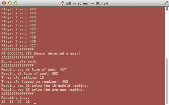
Debugging.
This issue came up during the final assembly of the new version. In the first version, a threshold was hard-coded. When the reading from the sensors in the goal return slots went below that threshold, that (supposedly) meant that the ball had broken the beam and a goal was registered.
It wasn’t perfect, but it worked. Then, we moved the table. Where the table used to be was dark, with very little natural light. Where the table is now however, there are large windows and skylights. As a result, the light levels of the room change very often. This meant that a hard-coded threshold wouldn’t work. Instead the microcontroller simply looks at a past reading, compares it to the current reading and decides whether a drop means a goal or not. So far it’s working pretty well (knock on wood).
The new design
After a couple of months of hard work redesigning the scoreboard (the receiver unit) as well as the under-table unit, I’m finally finished.
Here’s the under-table transmitter unit:
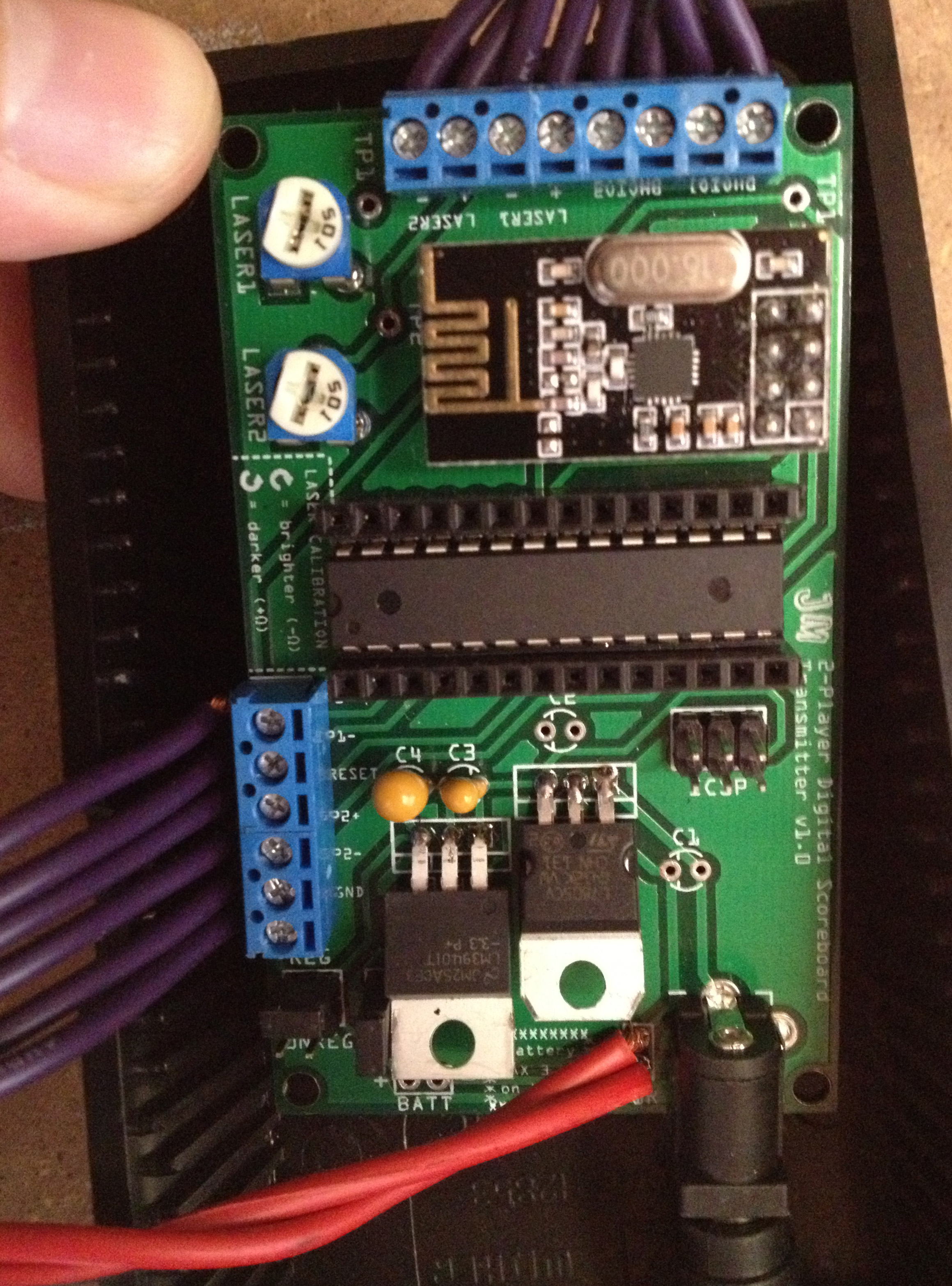
Click to view full-size.
And here are the features:
- ATmega328 running at 8MHz
- 5V and 3.3V regulators
- nRF24l01+ 2.4GHz wireless transceiver to communicate with hanging receiver unit above the table.
- Terminal blocks for easy connectivity (for lasers, photoresistors, and button controls)
- Trimpots to control laser diode brightness
- Protection resistor to ensure laser does not use too much current
- Laser on / off control: laser diodes are powered using pins on the ATmega328 allowing them to be turned off to save power.
- Power jack and battery connections.
- ICSP header for easier programming.
- Female headers connected to ATmega328 pins for future expansion / additional functionality.
Here is the over-table receiver unit:

Click to view full-size.
With its features:
- ATmega328 running at 8MHz (can also run at 16MHz)
- 3.3V regulator
- Power LED
- IDC connections for connecting 7-segment displays via ribbon cable.
- MAX7219 LED drivers
- nRF24l01+ 2.4GHz wireless transceiver
- Expansion header to add more LED displays for TIME digits.
- Female headers connected to ATmega328 pins for future expansion / additional functionality.
Other miscellaneous improvements include:
- New plastic enclosure for the bottom unit.
- New laser-cut acrylic faceplates for the top receiver unit (these hold the 7-segment displays in place behind the metal frame)
- Clear acrylic bottom on the receiver unit, which allows people to see the PCB and ribbon cables.
New Design Issues
AsNothing is perfect, and the new design still has a couple of minor issues. With the transmitter unit, there isn’t really a need for both a 5V and 3.3V regulator. When first designing the board, I had assumed that I was going to run the microcontroller at 16MHz, which would have required 5V. Instead, I ended up using 8MHz, so the 3.3V regulator alone would have sufficed (the 3.3V regulator was added in the first place because nRF24l01+ modules can only take up to 3.6V on the VCC pin).
The receiver unit also has a design issue. When I first designed it, I was assured that a simple voltage divider would have worked to bring the 5V down to 3.3V for the nRF24l01+ unit. However, after having the boards printed, I learned that it would not be able to supply enough current. I decided to replace the 5V regulator with a pin-compatible 3.3V one. The LED drivers are able to operate at that voltage, the 7-segment displays were just fine, the only change I needed to make was to bring the ATmega328 down from 16MHz to 8MHz.
Future Improvements
While the scoreboard has come a very long way, there are still a few things that I would change, aside from fixing the couple new design issues listed above.. The first would switch away from the ATmega328 to the ATmega32u4. The main reason for this is because of ATmega32u4’s built-in USB support. This would allow myself or other to simply take a USB cable and plug it into the scoreboard in order to update the programming. Depending on the current draw, it may even be able to power the whole board (but we’ll have to see).
Another feature I’d like to implement is digital screens. Now this one is something I’ve been looking at for a while, but the biggest problem I’ve had so far is finding a cheap screen that fits the scoreboard frame perfectly. I may end up going with a custom-designed frame, but that’s a ways off.
The most exciting new feature that I want to implement is a video replay system. I’ve played with this idea a little bit, even going as far as purchasing a PS3 eye cam (which can do 60FPS) and doing test recordings, but it’s still a long way away from becoming a reality at this point.
Thanks for reading! If you have any questions, feel free to post a comment or shoot me an email.
Hi, this is awesome. Are you selling these at all? I’d be really interested in one of these if so?
Tindie Series #2: Simon Says and Arduino Projects by Jeff Murchison | MakingSociety
Please start selling these. I’d be interested in one as well.
Hi Jeff..AWESOME JOB! I’ve been looking for months to find someone that has what I’ve been dreaming of. The only mods I’m looking for is a variable countdown timer (5/10/20min) and a period display. I’m going to use $30 Chinese dash cams for video feeds to the scoreboard. We already have the Hockey Lamp unit.
Are you interested in selling your PCBs and design info?
Todd,
Did you ever end up finishing your project? Would love to know how it ended up.
The cabinet is one inch thick and provides a good amount of sturdiness and durability. It is made in the United States and the Tornado brand of foosball tables is known for being one of the best out there. Foosball man durability is one of the main strengths of this table and you can count on it lasting for quite a long time.
Arduino-Powered Foosball Scoreboard (Part 1) | Murchlabs