
I finally finished the next version of my TinyLoadr AVR programming Shield – and it’s not a shield. It’s a standalone USB programmer, so you no longer have to have an extra Arduino laying around. The best part? It’s the same price as the shield was!
Read more to find out more about it, or visit my Tindie store to grab one for yourself!
Features at a glance
- Open source.
- Supports a wide range of AVRs (see list below)
- USB connector
- 16MHz clock source for all supported AVRs
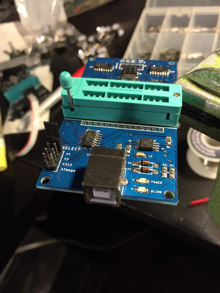
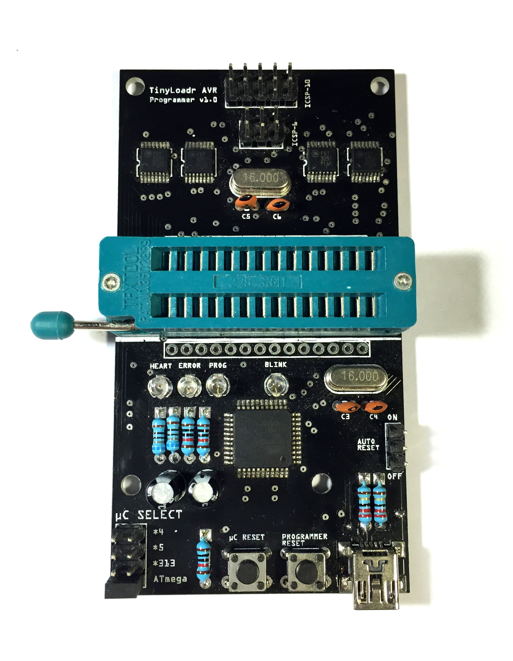
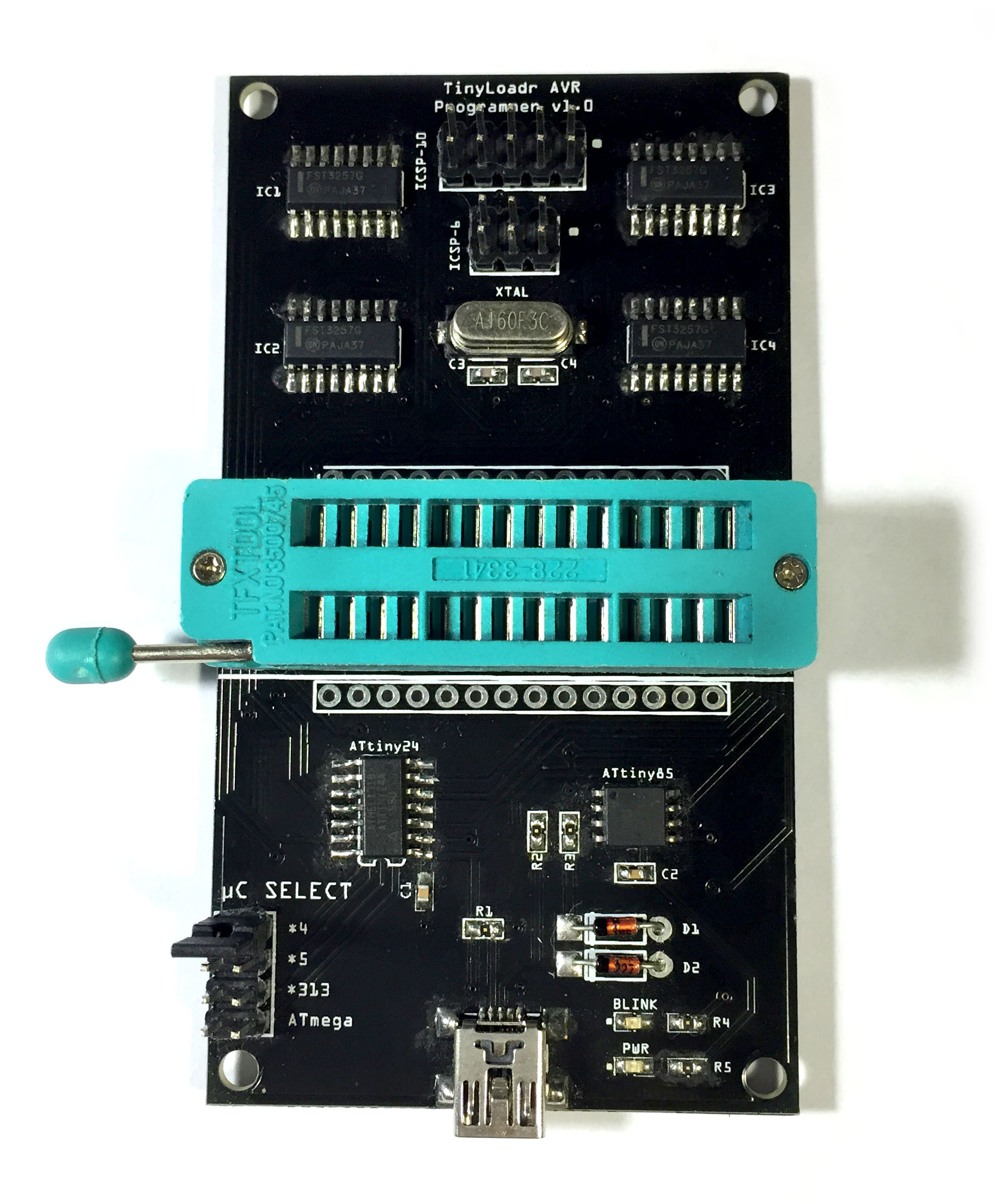
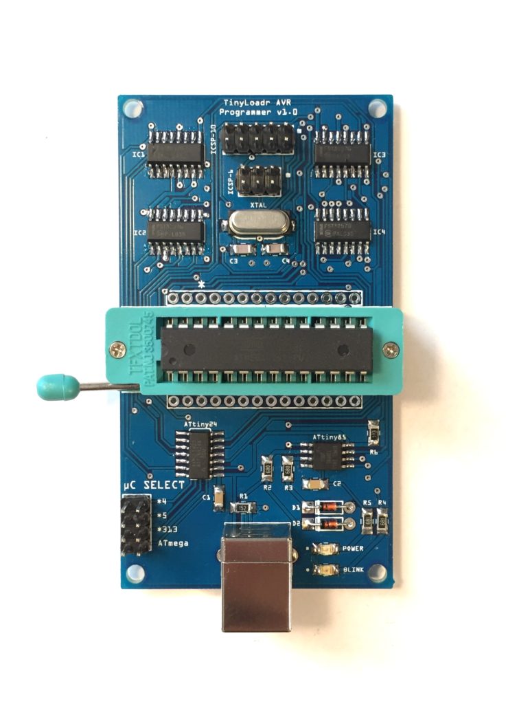
- One 28-pin ZIF socket
- A Blink LED to test your microcontrollers
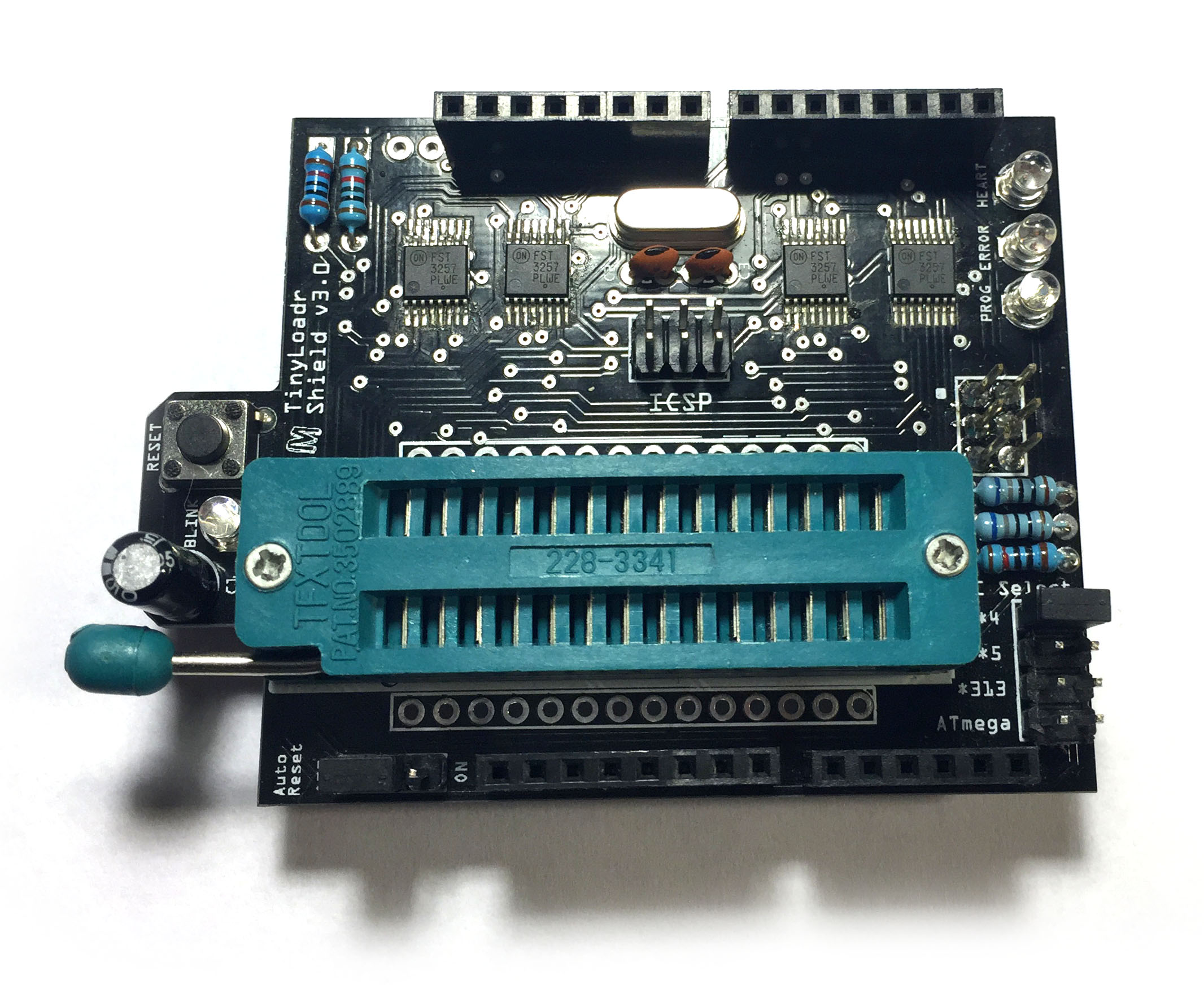
- 10 and 6-pin ICSP headers for programming target boards
- Can power target boards with 5V
- M3 (3.2mm) size mounting holes
- Easy to use for both beginners and advanced users
- Easy to use with both Arduino IDE and avrdude
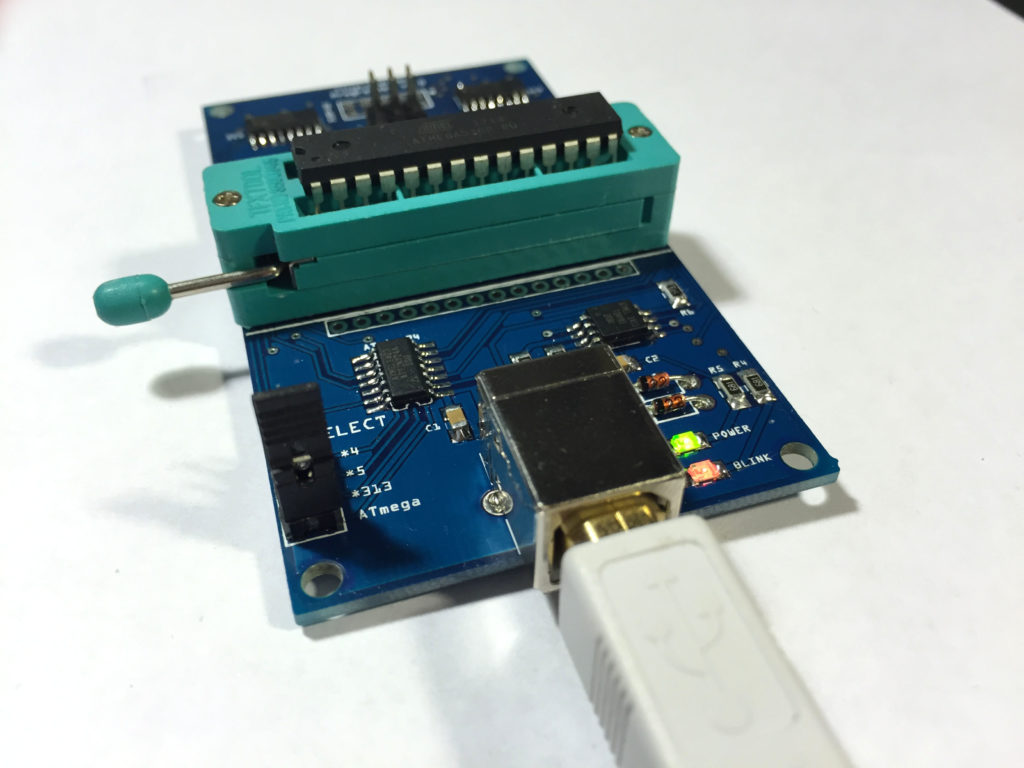
USB connector, power LED, and a Blink LED for testing your microcontrollers.
What microcontrollers are supported?
The following DIP microcontrollers are supported in the ZIF socket:
- ATtiny11
- ATtiny12
- ATtiny13
- ATtiny15
- ATtiny24
- ATtiny25
- ATtiny44
- ATtiny45
- ATtiny84
- ATtiny85
- ATtiny2313
- ATtiny4313
- ATmega8
- ATmega48
- ATmega88
- ATmega168
- ATmega328P
On target boards, any microcontroller that avrdude supports is supported, though Arduino cores may not exist for all of them. Any pin-compatible AVRs will also work (that is, one with the same pinout).
The programmer may not work with microcontrollers with more than 64K of flash (e.g, ATmega1281/1280/2561/2560).
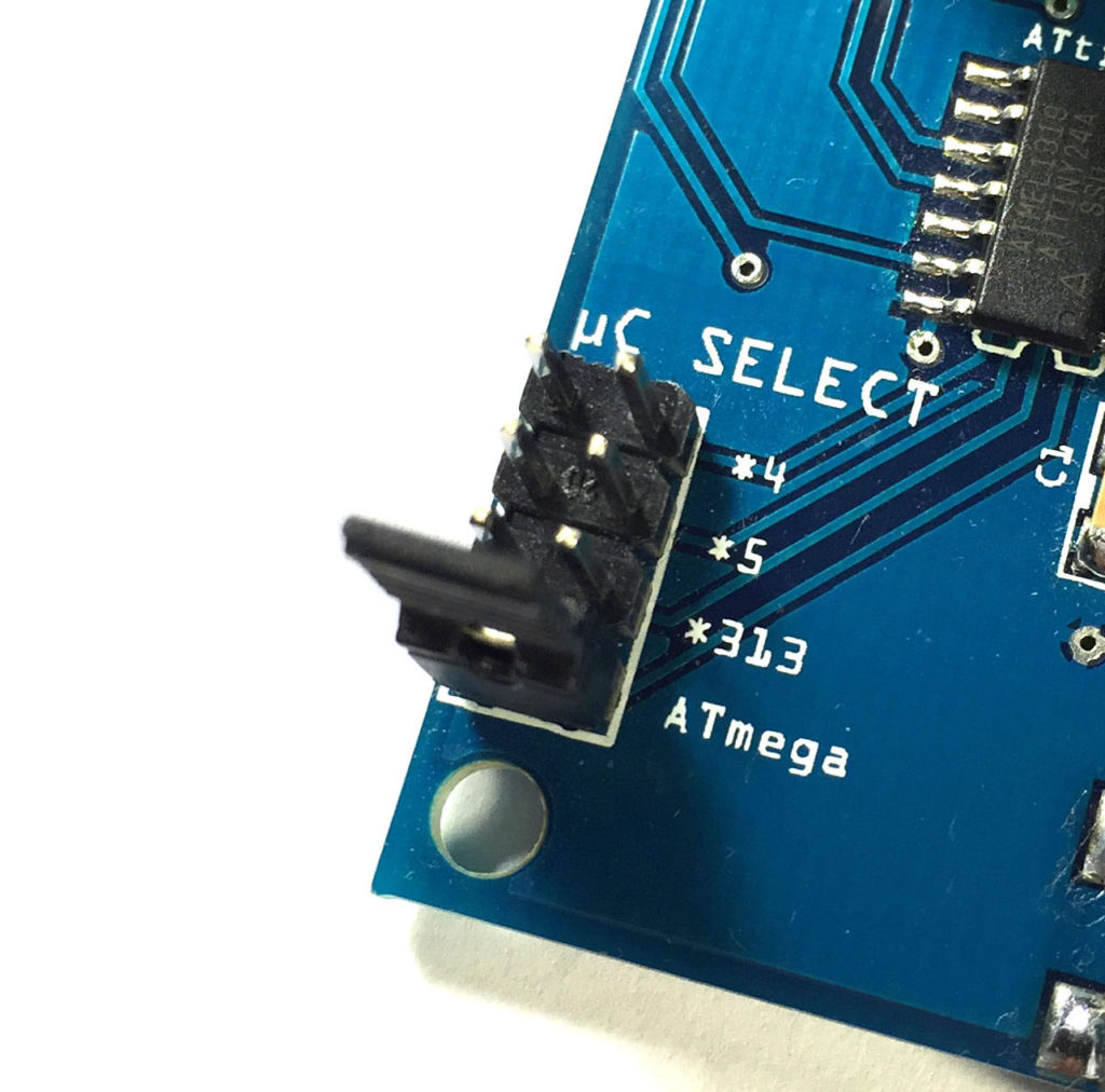
One jumper to select the microcontroller you want to program.
It’s pretty easy to use
The TinyLoadr AVR Programmer was designed to be very simple to use. When programming a microcontroller with the ZIF socket, you simply set the “uC Select” jumper to the appropriate microcontroller, and insert the microcontroller as shown in the photos. For programming with the ICSP headers, just attach your ICSP ribbon cable to the programmer and your target board and you’re ready to roll.
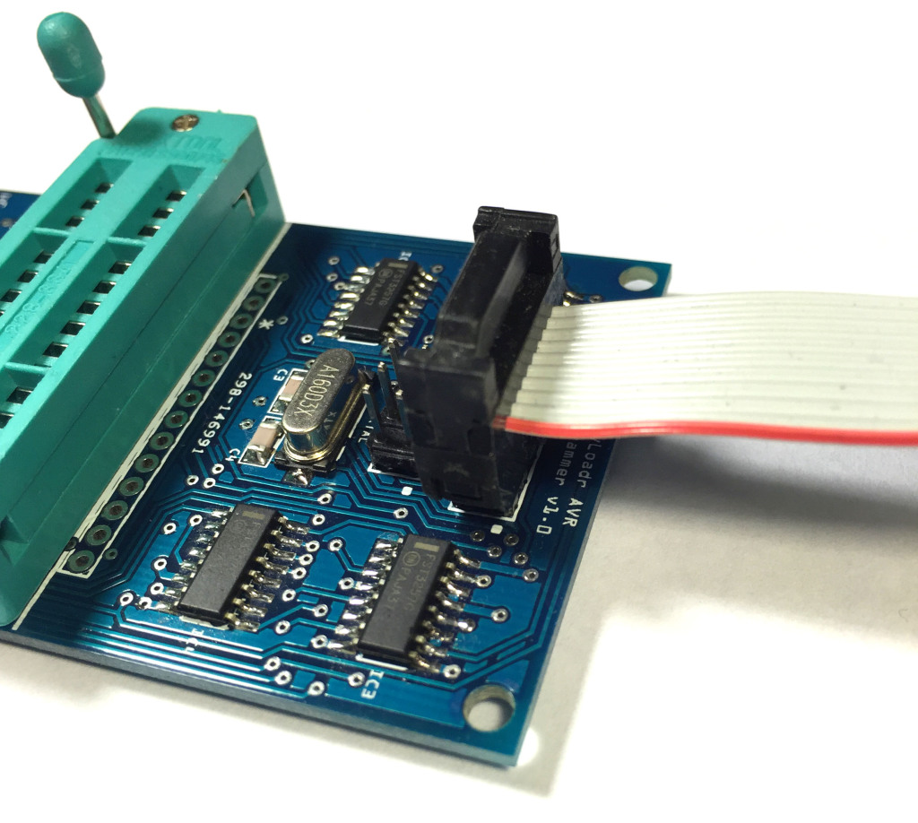
6 and 10-pin ICSP headers for programming other boards (ribbon cable not included).
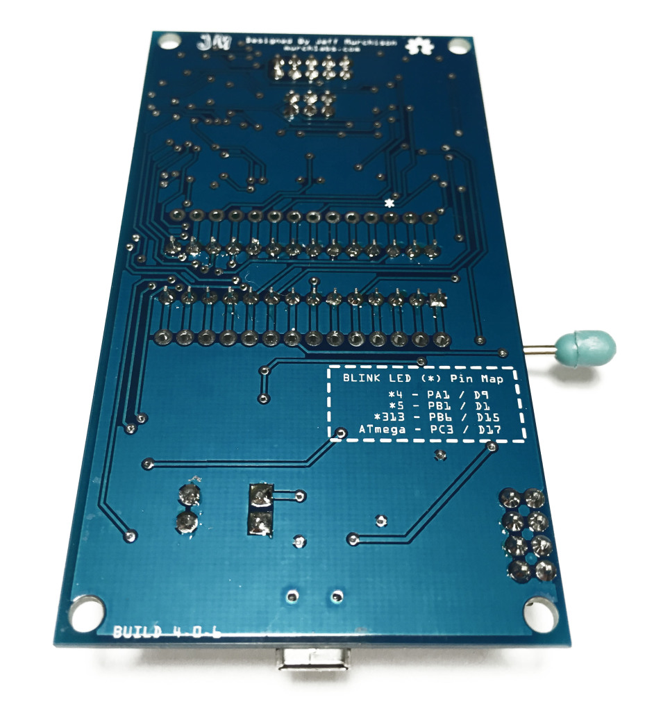
Legend on the bottom for the Blink LED.
2 years ago I designed my first PCB – an Arduino shield that made it easier for me to program ATMega and ATtiny microcontrollers with my Arduino. I called it the ArduinoISP Shield (later renamed to the TinyLoadr Shield to avoid any issue using the Arduino name). After building my own, I still had 9 PCBs left. I decided to order parts to build them and sell them on Tindie. I did, and people loved them. Over the next 2 years, I designed through 4 variations of the shield, adding new features and making it look nicer. Well, I’ve done it again, and I really hope people will like it.

The original TinyLoadr Shield (then called the ArduinoISP Deluxe Shield)
People will always find faults with their own work. Working in the motion graphics business, I see this a lot. Everyone is their biggest critic, and I’m no different. With the TinyLoadr Shield, there were two things that bugged me.
The first was the process of switching between different chips. I had banks of switches and a row of jumpers. Why I didn’t design it with more switches to get rid of those jumpers, I don’t know. I wanted it to be easier, so I started looking at electronic switches. I eventually started playing around with multiplexers. The first ones didn’t work because their resistance was too high. The second ones worked like a charm. Also, they were even cheaper than the old manual switches. I just needed something to control them, so I figured I could just throw a small microcontroller on there to handle that.
I actually built 2 prototype shields with multiplexers that would switch between microcontrollers using a single jumper. I never brought those models into production because the multiplexers I needed only came in SMD packages and I had no experience soldering SMD. I bought a hot air station and started learning. I also had no way of testing them fast and efficiently so I would have had to build them all instead of offering kits. These prototypes also allowed the ATtiny microcontrollers to use the 16MHz crystal as a clock source!

The first prototype without DIP switches.
The next prototype also had an ICSP header.
The second thing that bugged me though was the nature of the shield itself – it was a shield. It is useless without an Arduino. If you don’t have a spare Arduino then you have to take apart your existing project to use it. Also, you have to load the ArduinoISP sketch every time. It’s a small thing, but I grew to hate it. I figured it couldn’t be that hard to create an Arduino clone and integrate the existing shield wiring (I wired the traces on this thing by hand, no autorouter). So that’s what I did.
The first TinyLoadr AVR Programmer prototype.
The first prototype used an ATmega32u4 – the same used in an Arduino Leonardo. The main reason I chose the 32u4 is because it has built-in USB. With the other ATmega microcontrollers, I would have had to add a USB to Serial chip. With the 32u4, I just needed two 68 ohm resistors. The first prototype was really unstable. I’d used no decoupling capacitors in a vain attempt to save money, and coupled with me still being very new at SMD soldering and the packages being very tightly spaced, I had a lot of failed boards. In fact, the wall near my desk still bares a perfect imprint of the corner of one of my boards.

The second prototype, after moving things around and switching to SMD parts.
The second prototype was a big change. In the first, I had used as many through hole components as I could not only because I got them at a better price than I got SMD ones in small quantities, but because I was also very inexperienced with SMD. It was also one of the ugliest boards I think I’ve ever made. The second used almost no through hole components, save for the ZIF socket, the headers, and the buttons. Unfortunately I continued to suck at soldering the tight packages of the ATmega32u4 and the multiplexers. The price of the ATmega32u4 in small quantities was also prohibitive.
The third prototype.
The third prototype switched the package type of the multiplexers to a wider one. Unfortunately this meant they had to be rearranged. Holy crap that was a lot of work. South of the ZIF socket, I also got rid of the ATmega32u4. Unfortunately it didn’t come in a wider package, and I wasn’t sure if my design wasn’t to blame, so I decided to change things up. I found guides online for turning an ATtiny45/85 into a USBtinyISP AVR programmer. You only needed 8 components, too. Unfortunately I had no spare pins for controlling the multiplexers so I threw an ATtiny24 (which had exactly enough digital i/o pins) on there to control things. The only flaw with this prototype was that it was missing a pullup resistor on the ATtiny85 so it would randomly not work at times. D’OH.

The fourth prototype and current production version.
The fourth prototype is the first version that I started selling. I added the necessary pullup resistor and I also changed all the resistors, LEDs, and capacitors from 0603-sized packages to 1206. The reason for this is that while I can solder 0603 fine, they are quite small and take longer and more effort to do properly. Also they don’t have markings on them whereas 1206 ones do so if I drop one, I still know what value it is.
The next version is essentially the same. The only change is the USB connector (and the component placement, to accommodate the new connector). It uses USB-B connectors because, well, they’re through hole. For me, the hardest part of the previous version to solder was the USB connector. I just couldn’t seem to do it very well, not with flux, not with fine solder, not with solder paste, not with hot air, not with thick soldering iron tips, and not with thin ones either.
The current version with a USB-B connector.
Maybe I’ll go back to mini or even micro usb in a future version but I’ll see how this one fares. I may also change the jumper to a slide switch. The jumper is a leftover of the first prototype. On it, when you made the change between microcontrollers, it flashed its LEDs as a confirmation. I did this as the microcontroller that handled the programming was also the one that handled the multiplexers, and I didn’t use interrupts.
The newest prototype doesn’t have that issue (it has instant response) so a slide switch would work well. The only concern I have is that the slide switches are relatively easy to move. If you accidentally bumped it you risk applying power to the wrong pins of your microcontroller and breaking them or the programmer.
My next prototype has pins and drills for two USB connectors – the Mini USB connector is back, hidden under the USB-B connector. If it works, then I can offer people an option when buying their programmer – Mini USB or USB-B? I could try out Micro USB as well, I think that may be better than Mini USB.
I just got mine, with the USB-B connector, and it’s awesome.
Popped in an ATTiny44a, set it up with the Arduino IDE, sent over a blink program, and I’ve got a blinking LED.
It’s surprisingly hard to find a programmer for AVR chips that is affordable and all-in-one. Thanks for designing/selling these!
Can this be used to program chips at 3.3v? for example atmega328 3.3v using 8mhz crystal or internal oscillator? I was all set to buy your last version when i found this one had come out, great work!
Hey Dale,
Sorry for the late reply, I never got a notice about the comment.
For now, it can only be used for 5v chips. The ICSP headers use 5v for power and logic, and the ZIF socket is a little below 5v due to the voltage drop from the multiplexers but I wouldn’t rely on using it for microcontrollers that can only take up to 3.3v.
Microcontrollers can still use their internal oscillators without issue, there shouldn’t be any problem with having the external crystal attached at the same time. If you want to use an external crystal that isn’t 16MHz then you will either have to physically replace it or use a different clock divider when setting your fuses.