
These are the build instructions for the Simon Says game kit v2.0. While this kit is for beginners, these instructions assume that the user has a basic knowledge of soldering. If you do not know how to solder, then check out this great guide by Sparkfun before continuing.
Note: These instructions are for v2.0 boards. All boards are labeled with “Simon Says” followed by a version number. If you are looking for instructions for v1.0 and v1.5 boards, look here.
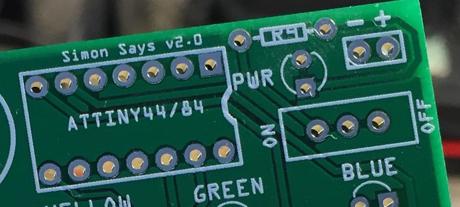
The v2.0 boards also have a spot for an on/off switch whereas the previous versions did not.
Another thing to note, the game does make repetitive noises by default, which can annoy some. To enable silent mode, just hold the button below the red LED while turning the game on.
———
The following tools are used in this tutorial:
- Soldering iron (required)
- Solder (required)
- Wire/side cutters (required)
- Desktop vice (optional, but very, very useful).
———
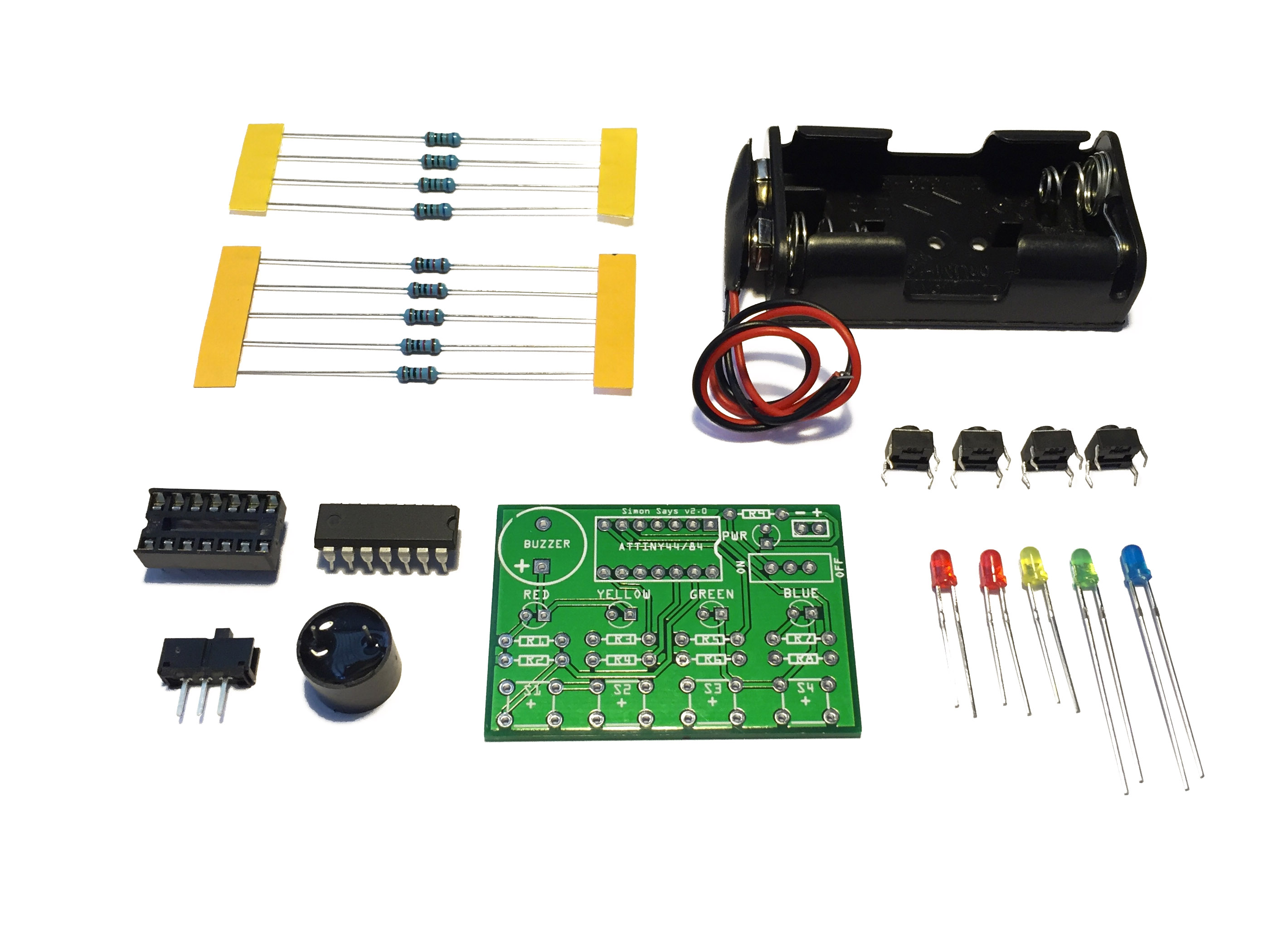
First, ensure that you have all of the pieces of your kit. The kit includes:
- 1x Simon Says PCB
- 1x 2xAA Battery holder (batteries not included)
- 1x ATtiny44A (pre-programmed)
- 1x 14-pin socket
- 4x Tactile pushbuttons
- 4x Bright LEDs (multiple colours – red, green, blue, and yellow)
- 1x Red power LED
- 1x Piezo buzzer
- 5x 10K ohm resistors
- 4x 680 ohm resistors
You will also need two AA batteries to power the game and optionally, a piece of double sided tape or some glue to secure the board to the battery pack.
———
Click the photos for higher-resolution versions.
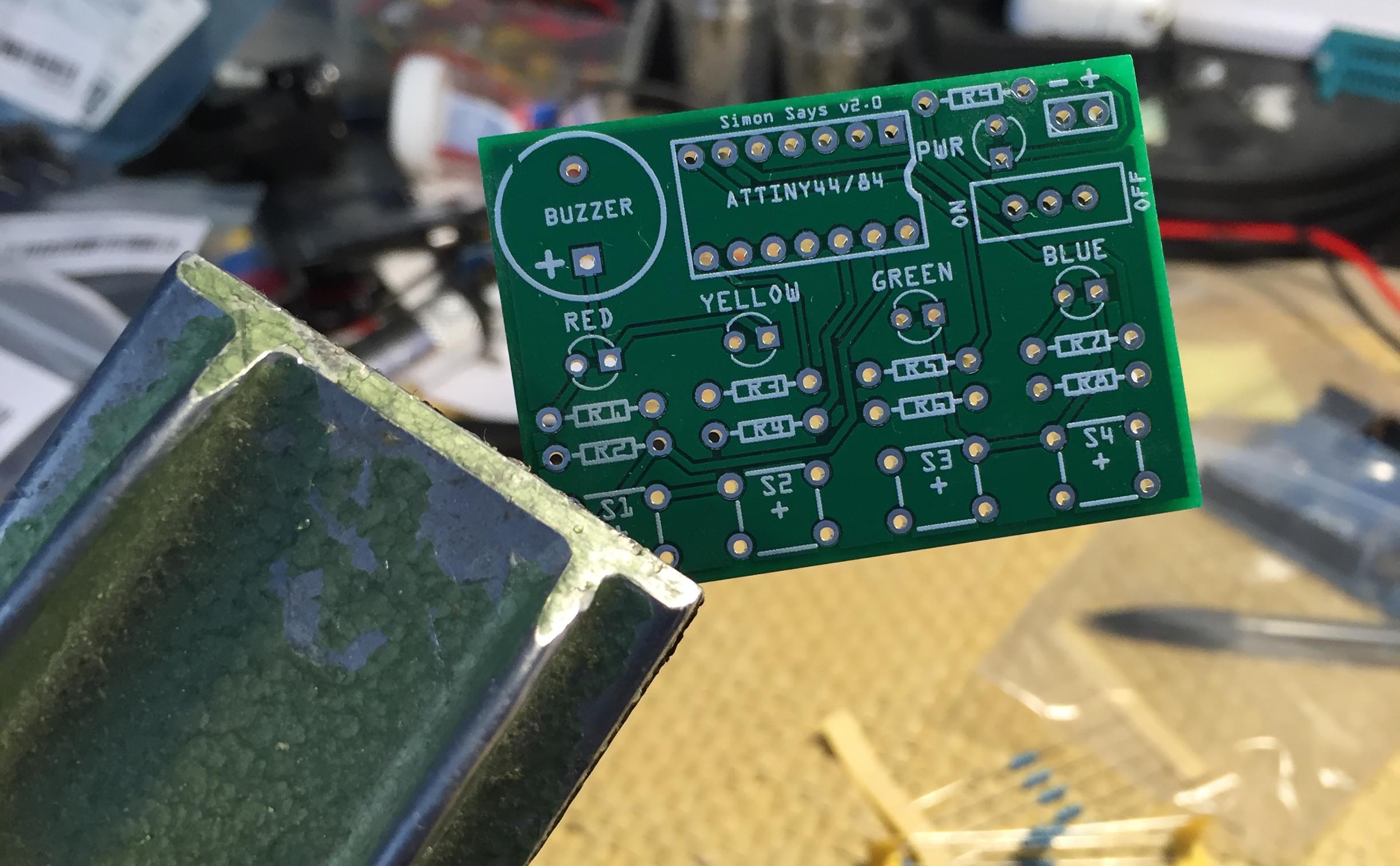
Start by placing your PCB into a desktop vice with the silkscreen side up.
When soldering to a PCB, it is a good idea to start with low-profile components, working your way up to the ‘taller’ components.
We are going to start by adding the 10K ohm resistors. They will fit into the R2, R4, R6, R7, and R8 spots. The resistors in your kit may be labeled, however they can also be identified by the colour bands – brown, black, black, red, brown. Another way of identifying them is by using a multimeter to measure their resistance.
Start by bending the leads on your resistors at a 90 degree angle. Try and leave a bit of a wide bend like in the photo below. This will help the resistors stay in place a little better when the PCB is upside-down.

Insert the first resistor. Orientation is not important, as resistors do not have polarity, so don’t worry about inserting it “backwards.” If it is loose-fitting, then bend the leads on the other side so it can stay in place without falling out.


Remove the PCB from the vice and flip it over. If you can’t get your components to stay in place when upside down, try bending the leads. If that still doesn’t do the trick, then use a little bit of tape to hold them to the board. Solder the resistor to the board, and repeat this process for the rest of the 10K ohm resistors in spots R4, R6, R7, and R8. When you are done, it should look like this.


Now we need to clip the excess leads. Using wire cutters, cut the excess wire off of the resistors as as close to the top of the solder joint as you can. Note that excess wire may go flying into your face when clipped, so either wear safety goggles, or hold onto the excess wire while you snip it. You should continue to cut the excess wire off of components as you go along.

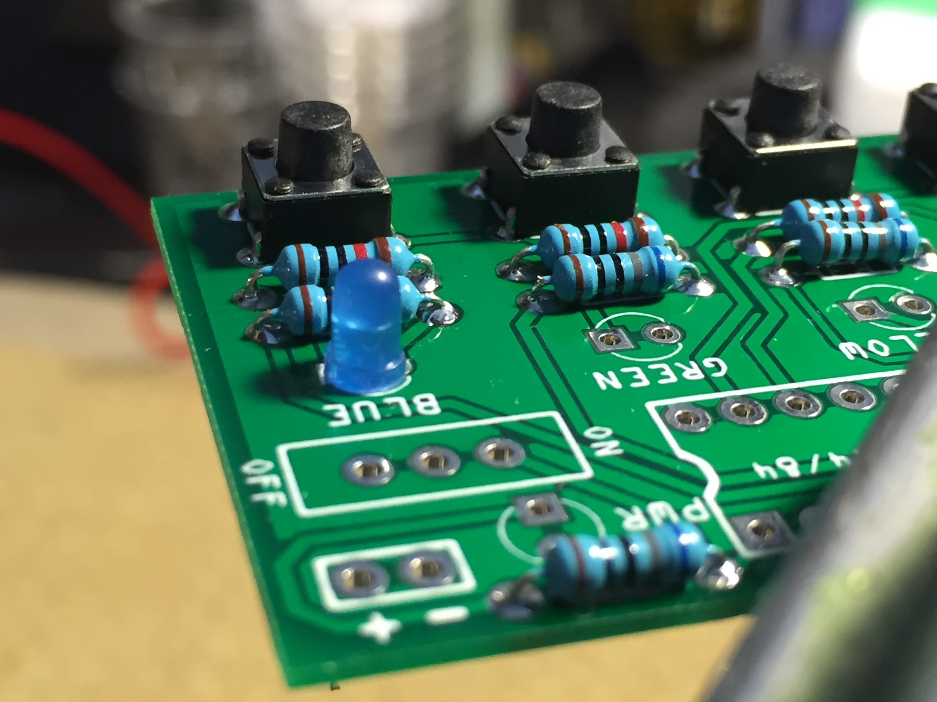
We are now going to add the 680 ohm resistors. They will fit into the remaining resistor slots (R1, R3, R5, and R9). Insert them and solder them in place.

Time to insert the pushbuttons. They should snap into and stay in place very easily. Insert all of the pushbuttons, flip the PCB over, and solder them.


Time to add the LEDs. There should be two red, and one each of yellow, blue, and green.

When inserting LEDs, remember that LEDs are polarized and must be inserted correctly in order to work properly. If you look at your LED, you will notice that one lead is shorter than the other. The longer lead (the anode) will go into the square hole, and the shorter lead (the cathode) will go into the round hole. Solder all of the coloured LEDs in their respective spots on the PCB. Use the second red LED for the power LED.
If you look even more closely at the LED itself, you should notice that the side with the short lead is slightly flat, and lines up with the white silkscreen on the PCB.
Like the resistors, you can bend the LEDs leads to keep it from falling out while you are soldering it. Alternatively, you can place a finger under the LED holding it in place, while also holding your solder.


Up next is the IC socket. When inserting the socket, note the small half-circular cutout on the right of the socket should align with the half-circle in the silkscreen See the photo below for clarification.

To get the socket to stay in place when flipped over, bend the pins on two opposing corners.

Then, solder another pair of opposing corners. Un-bend the pins and solder the rest.
On the piezo buzzer, there is a small “+” symbol. Line it up with the plus symbol on the PCB to ensure that you are inserting it properly. The buzzer will not work if it is inserted backwards.

To hold the buzzer in place, you might be able to get away with fitting it in your vice with the PCB. If not, use your hands or tape.

We’re almost done! Next up is the on/off switch. It can be inserted in any orientation.

Just like before, you can either bend the leads, hold it with tape, or hold it with your hand while you solder it.

The last item to solder is the leads from the battery pack. You may have leads which clip onto a battery pack, or the leads may be connected directly to your battery pack. If they clip on, clip them on after you have soldered them to the PCB.
Trim the leads of the battery pack to about 4.5cm and strip the ends, leaving about 3mm of wire exposed. Tin the leads with some solder.
Insert the red lead into the “+” hole and solder it. Then insert the black lead into the “-” hole and solder it.
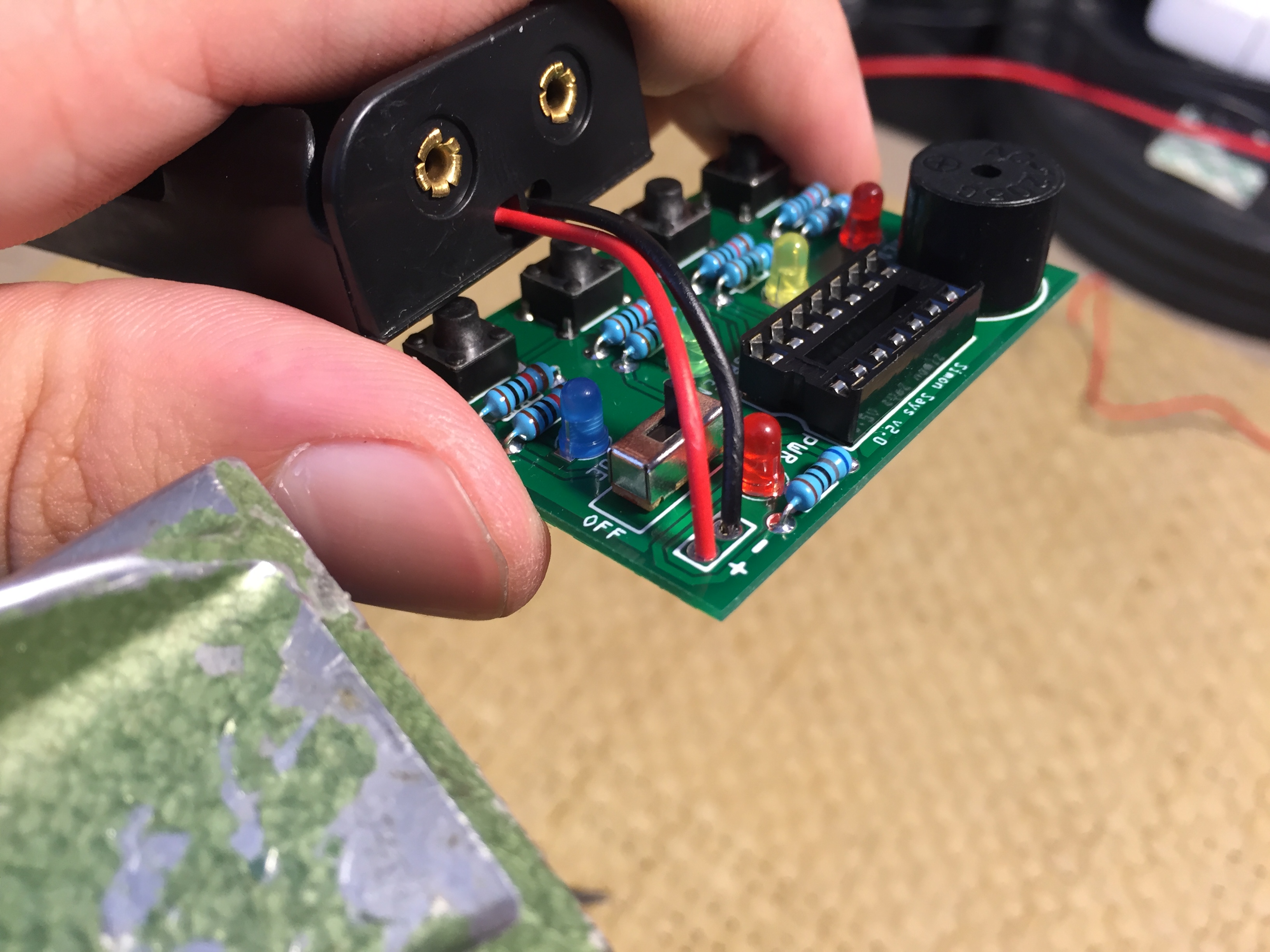
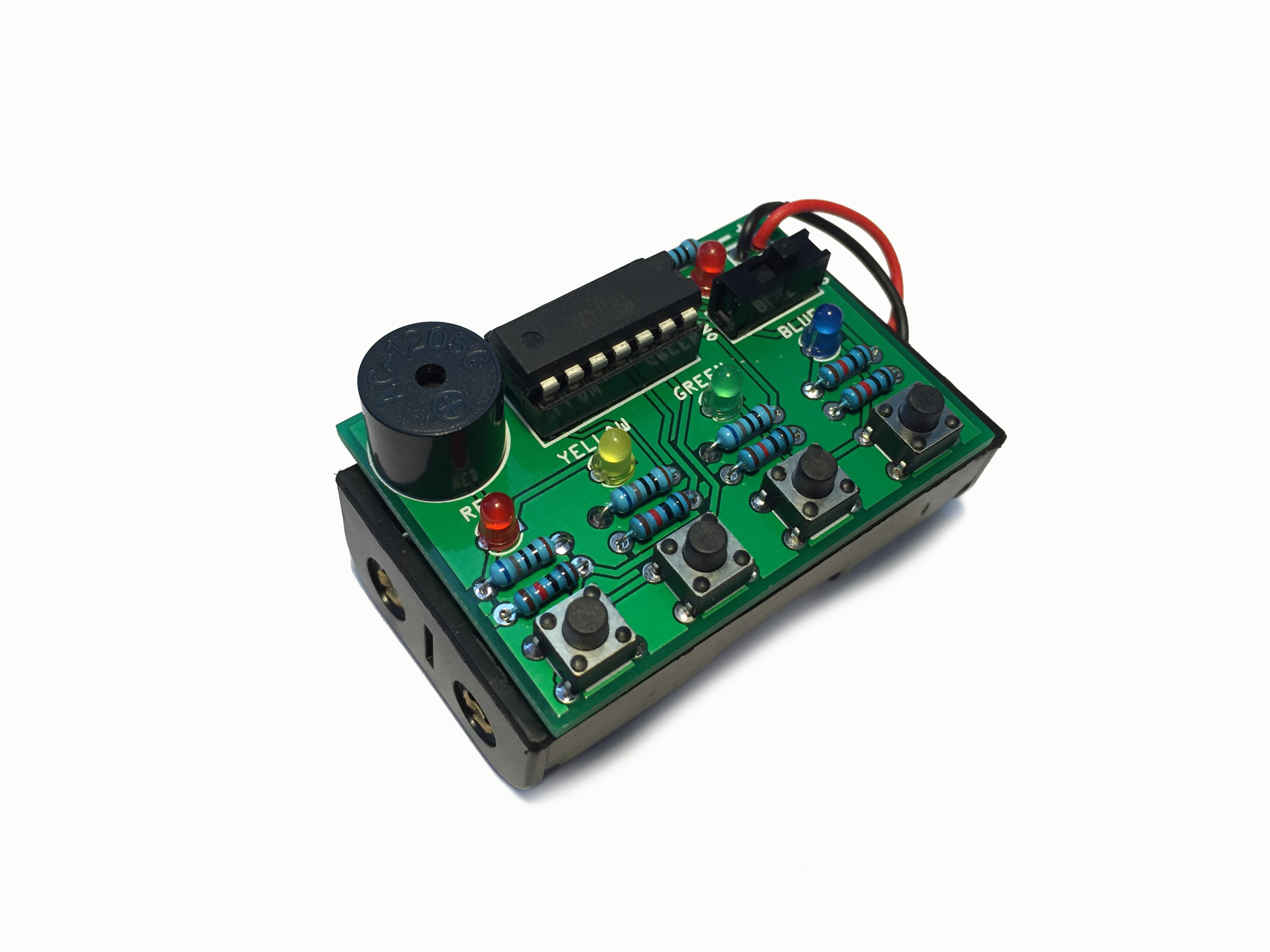
The last thing to do is to insert the microcontroller into the socket. Ensure that you line up the half-circle cutout on the microcontroller with the half-circle cutout on the socket. Failure to insert the microcontroller properly may damage it. You may have to bend the pins of the microcontroller slightly inward in order to fit it in the socket. The end product should look like this.

Go ahead and test it out! Insert some fresh AA batteries into the pack and turn the switch on.

The power LED should light up and you should hear the startup noise coming from the buzzer, indicating a new game has started. If the LEDs do not light up, or the buzzer doesn’t work, then double-check all of your solder joints. Also ensure that your batteries are new or charged (if using rechargeable batteries).
If you have some double sided tape (not included), feel free to stick some on the back of the PCB in order to keep it attached.

And with that, you’re done! Congratulations! Remember, this kit is open source. If you want to change the gameplay in any way, you’re absolutely welcome to do so. You can find the source code here along with a small tutorial on how to reprogram the microcontroller using an Arduino (tutorial coming very soon).
Also note, if you don’t want to hear the buzzer tones, just hold down the RED button when you switch the game on and it will start up in silent mode.
Build Instructions: Simon Says Game Kit | Arduino Projects